Searchable explanations of IFR enroute airports, radio aids, airspace, airways, foreign areas, and terrain contours.
Controlled airspace consists of those areas where some or all aircraft are subjected to air traffic control within the following airspace classifications of A, B, C, D, & E.
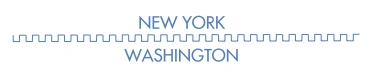
Air Route Traffic Control Centers (ARTCC) are established to provide Air Traffic Control to aircraft operating on IFR flight plans within controlled airspace, particularly during the enroute phase of flight. Boundaries of the ARTCCs are shown in their entirety using the symbol below.
ARTCC boundary symbol — source page 67.
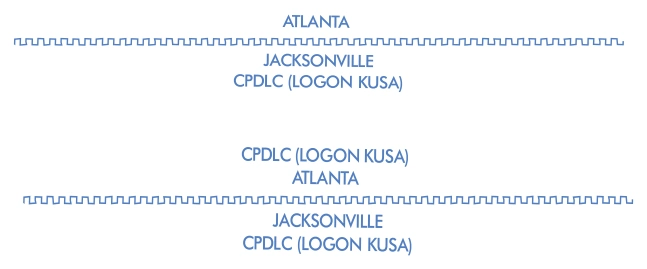
ARTCC CPDLC boundary examples — Atlanta/Jacksonville, logon KUSA — source page 67.
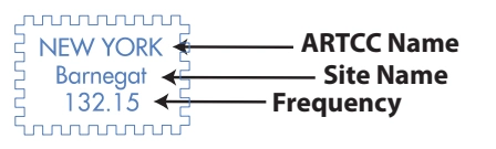
ARTCC remote-site box — New York Center / Barnegat / 132.15 — source page 67.
UNCONTROLLED AIRSPACE
SPECIAL USE AIRSPACE
Special Use Airspace (SUA) confines certain flight activities, restricts entry, or cautions other aircraft operating within specific boundaries. SUA areas are shown in their entirety, even when they overlap, adjoin, or when an area is designated within another area. SUA with altitudes from the surface and above are shown on the IFR Enroute Low Altitude Charts. Similarly, SUA that extends above 18,000' MSL are shown on IFR Enroute High Altitude Charts. IFR Enroute Charts tabulations identify the type of SUA, ID, effective altitudes, times of use, controlling agency and the panel it is located on. Users need to be aware that a NOTAM addressing activation will NOT be issued to announce permanently listed times of use.
AIRSPACE INFORMATION CONTROLLED AIRSPACE Controlled airspace consists of those areas where some or all aircraft are subjected to air traffic control within the following airspace classifications of A, B, C, D, & E. Air Route Traffic Control Centers (ARTCC) are established to provide Air Traffic Control to aircraft operating on IFR flight plans within controlled airspace, particularly during the enroute phase of flight. Boundaries of the ARTCCs are shown in their entirety using the symbol below. ARTCC Name Site Name Frequency Air Route Traffic Control Center (ARTCC) When Controller Pilot Data Link Communication (CPDLC) exists for an ARTCC, the text CPDLC (LOGON KUSA) will be shown parallel to the boundary above or below the ARTCC identification as shown below. Air Route Traffic Control Center (ARTCC) with Controller Pilot Data Link Communication (CPDLC) The responsible ARTCC Center names are shown adjacent and parallel to the boundary line. ARTCC sector frequencies are shown in boxes outlined by the same symbol. ARTCC Name Site Name Frequency ARTCC Remoted Sites with discrete VHF and UHF frequencies Class A Airspace is depicted as open area (white) on the IFR Enroute High Altitude Charts. It consists of airspace from 18,000 Mean Sea Level (MSL) to FL600. Class B Airspace is depicted as screened blue area with a solid line encompassing the area. Class C Airspace is depicted as screened blue area with a dashed line encompassing the area with a letter “C” enclosed in a box following the airport name. Class B and Class C Airspace consist of controlled airspace extending upward from the surface or a designated floor to specified altitudes, within which all aircraft and pilots are subject to the operating rules and requirements specified in the Federal Aviation Regulations (UHF) 71. Class B and C Airspace are shown in abbreviated forms on IFR Enroute Low Altitude Charts. A general note adjacent to Class B airspace refers the user to the appropriate VFR Terminal Area Chart. Class D Airspace (airports with an operating control tower) are depicted as open area (white) with a letter “D” enclosed in a box following the airport name. Class E Airspace is depicted as open area (white) on the IFR Enroute Low Altitude Charts. It consists of airspace below FL180. UNCONTROLLED AIRSPACE Class G Airspace within the United States extends to 14,500’ MSL. This uncontrolled airspace is shown as screened brown. SPECIAL USE AIRSPACE Special Use Airspace (SUA) confines certain flight activities, restricts entry, or cautions other aircraft operating within specific boundaries. SUA areas are shown in their entirety, even when they overlap, adjoin, or when an area is designated within another area. SUA with altitudes from the surface and above are shown on the IFR Enroute Low Altitude Charts. Similarly, SUA that extends above 18,000' MSL are shown on IFR Enroute High Altitude Charts. IFR Enroute Charts tabulations identify the type of SUA, ID, effective altitudes, times of use, controlling agency and the panel it is located on.
Source page 68
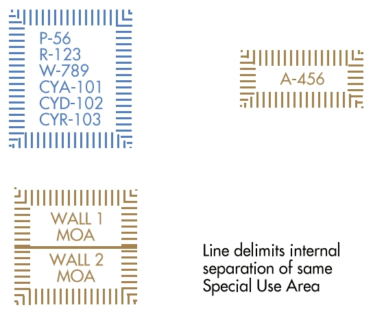
Special-use-airspace boxes — high/low P/R/W, low-only MOA/A, internal boundary — source page 68.
High and Low | Low Altitude Only
P - Prohibited Area | MOA - Military Operations Area
R - Restricted Area | A - Alert Area *
W - Warning Area |
* Alert Areas do not extend into Class A, B, C and D airspace, or Class E airport surface areas.
See Airspace Tabulation on chart for complete information.
OTHER AIRSPACE
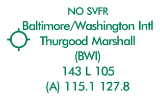
Baltimore/Washington International (BWI) airport-data example — source page 68.
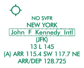
John F. Kennedy International (JFK) airport-data example — source page 68.
Mode C and ADS-B Out 30-NM boundary — source page 68.
INSTRUMENT AIRWAYS
The FAA has established two fixed route systems for air navigation. The VOR and LF/MF system-designated from 1,200' Above Ground Level (AGL) to but not including FL 180 is shown on IFR Enroute Low Altitude Charts, and the Jet Route system designated from FL 180 to FL 450 inclusive is shown on IFR Enroute High Altitude Charts.
VOR LF/MF AIRWAY SYSTEM (IFR LOW ALTITUDE ENROUTE CHARTS)
In this system VOR airwaysairways based on VOR or VORTAC NAVAIDsare depicted in black and identified by a "V" (Victor) followed by the route number (e.g., "V12").
Cookie Preferences
We use cookies to operate this website, improve performance, understand site traffic, and personalize your experience. Essential cookies are always active because they are required for the website to function.
Required for basic site functionality and security.
Help us understand how visitors use the website so we can improve it.
May be used for advertising, remarketing, or social media features.
You can update your choices anytime using Cookie Settings. View Privacy Policy