User-friendly explanations of instrument approach charts, planviews, profiles, minimums, airport diagrams, departures, arrivals, and visual procedures.
Doubtful accuracy symbol following an obstacle elevation — source page 112.
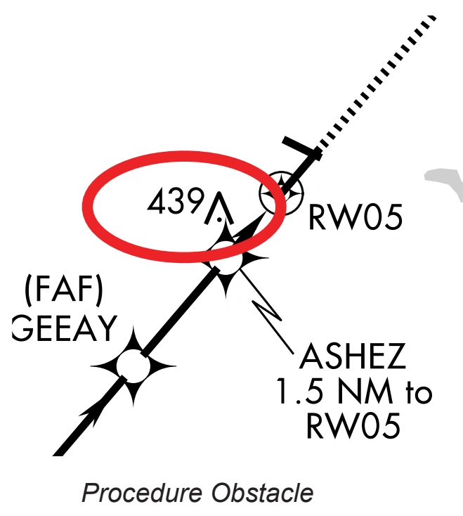
Procedure obstacle on an instrument approach chart — source page 112.
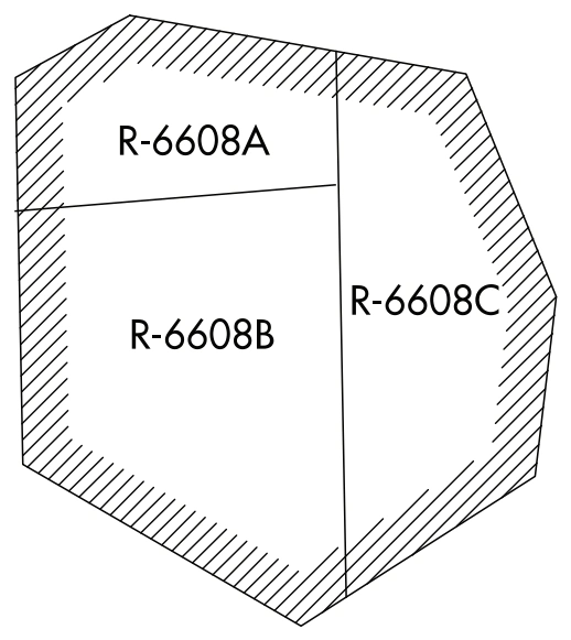
Special-use-airspace depiction — R-6608A, R-6608B, and R-6608C — source page 112.
SUAs consists of that airspace wherein activities must be confined because of their nature, or wherein limitations are imposed upon aircraft operations that are not a part of those activities, or both. These are prohibited areas, restricted areas, warning areas, Military Operations Areas (MOAs), and alert areas. SUA that falls within the area of coverage of the instrument approach procedure chart are shown only when designated by the approving authority.
Air Defense Identification Zone (ADIZ)
ADIZ is an area of airspace in which the identification, location, and control of aircraft is required in the interest of national security. When designated by the approving authority, ADIZ boundaries that fall within the area of coverage of the chart are shown.
Contiguous U.S. ADIZ boundary symbol — source page 112.
Minimum Safe Altitude (MSA)
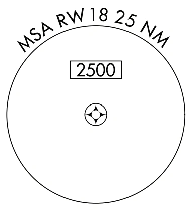
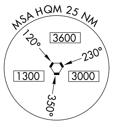
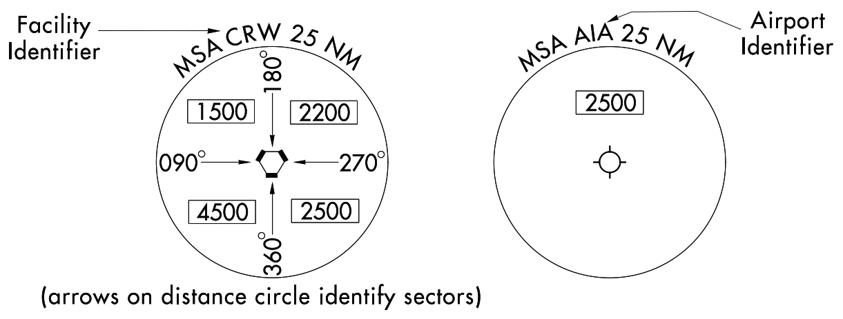
MSAs are published for emergency use on IAP charts. MSAs appear in the planview of all IAPs except on approaches for which a Terminal Arrival Area (TAA) is used. The MSA is based on the primary NAVAID, waypoint, or airport reference point on which the IAP is predicated. The MSA depiction on the approach chart contains the identifier of the NAVAID/waypoint/airport used to determine the MSA altitudes. MSAs are expressed in feet above mean sea level and normally have a 25 NM radius; however, this radius may be expanded to 30 NM if necessary to encompass the airport landing surfaces. Ideally, a single sector altitude is established and depicted on the planview of approach charts; however, when necessary to obtain relief from obstructions, the area may be further sectored and as many as four MSAs established. When established, sectors may be no less than 90° in spread. MSAs provide 1,000 feet clearance over all obstructions but do not necessarily assure acceptable navigation signal coverage.
Minimum Safe Altitude circle — RWY 18, 25 NM, 2500 — source page 112.
Sectorized Minimum Safe Altitude circle — HQM, 25 NM; 120°/230°/350° sectors at 3600/3000/1300 — source page 112.
Minimum Safe Altitude examples — CRW facility-identifier sector MSA and AIA airport-identifier MSA — source page 112.
Obstacles Procedural obstacles specifically indicated for charting by the approving authority will be charted. Obstacles identified as vegetation or ships will be indicated by a doubtful accuracy symbol following the elevation value. Procedure Obstacle Special Use Airspace (SUA) SUAs consists of that airspace wherein activities must be confined because of their nature, or wherein limitations are imposed upon aircraft operations that are not a part of those activities, or both. These are prohibited areas, restricted areas, warning areas, Military Operations Areas (MOAs), and alert areas. SUA that falls within the area of coverage of the instrument approach procedure chart are shown only when designated by the approving authority. Air Defense Identification Zone (ADIZ) ADIZ is an area of airspace in which the identification, location, and control of aircraft is required in the interest of national security. When designated by the approving authority, ADIZ boundaries that fall within the area of coverage of the chart are shown. Minimum Safe Altitude (MSA) MSAs are published for emergency use on IAP charts. MSAs appear in the planview of all IAPs except on approaches for which a Terminal Arrival Area (TAA) is used. The MSA is based on the primary NAVAID, waypoint, or airport reference point on which the IAP is predicated. The MSA depiction on the approach chart contains the identifier of the NAVAID/waypoint/airport used to determine the MSA altitudes. MSAs are expressed in feet above mean sea level and normally have a 25 NM radius; however, this radius may be expanded to 30 NM if necessary to encompass the airport landing surfaces. Ideally, a single sector altitude is established and depicted on the planview of approach charts; however, when necessary to obtain relief from obstructions, the area may be further sectored and as many as four MSAs established. When established, sectors may be no less than 90° in spread. MSAs provide 1,000 feet clearance over all obstructions but do not necessarily assure acceptable navigation signal coverage. Single MSA Multiple MSA’s
Source page 113
Terminal Arrival Areas (TAAs)
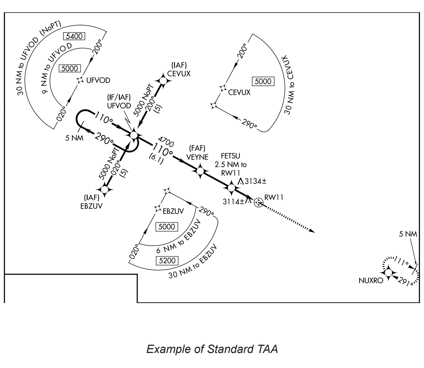
The TAA icons will be positioned in the planview relative to their relationship to the procedure. The icon will not have feeder routes, airways, or radar vectors depicted. The TAA provides a transition from the enroute structure to the terminal environment with little required pilot/air traffic control interface for aircraft equipped with Area Navigation (RNAV) systems. A standard TAA has three areas: straight-in, left base, and right base. The arc boundaries of the three areas of the TAA are published portions of the approach. A TAA provides minimum altitudes with standard obstacle clearance when operating within the TAA boundaries. TAAs are primarily used on RNAV approaches but may be used on an ILS approach when RNAV is the sole means for navigation to the IF; however, they are not normally used in areas of heavy concentration of air traffic.
Standard Terminal Arrival Area chart example — source page 113.
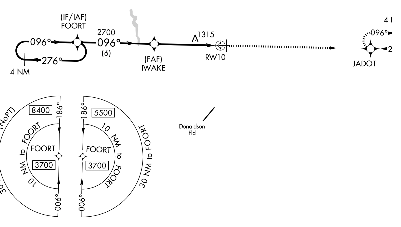
Non-standard TAAs may also be published; i.e., one base leg, no base legs.
Non-standard Terminal Arrival Area chart example — source page 113.
Terminal Arrival Areas (TAAs) The TAA icons will be positioned in the planview relative to their relationship to the procedure. The icon will not have feeder routes, airways, or radar vectors depicted. The TAA provides a transition from the enroute structure to the terminal environment with little required pilot/air traffic control interface for aircraft equipped with Area Navigation (RNAV) systems. A standard TAA has three areas: straight-in, left base, and right base. The arc boundaries of the three areas of the TAA are published portions of the approach. A TAA provides minimum altitudes with standard obstacle clearance when operating within the TAA boundaries. TAAs are primarily used on RNAV approaches but may be used on an ILS approach when RNAV is the sole means for navigation to the IF; however, they are not normally used in areas of heavy concentration of air traffic. Example of Standard TAA Non-standard TAAs may also be published; i.e., one base leg, no base legs. Example of Non-Standard TAA
Cookie Preferences
We use cookies to operate this website, improve performance, understand site traffic, and personalize your experience. Essential cookies are always active because they are required for the website to function.
Required for basic site functionality and security.
Help us understand how visitors use the website so we can improve it.
May be used for advertising, remarketing, or social media features.
You can update your choices anytime using Cookie Settings. View Privacy Policy