
Chapter 16
Transition to Jet-Powered Airplanes
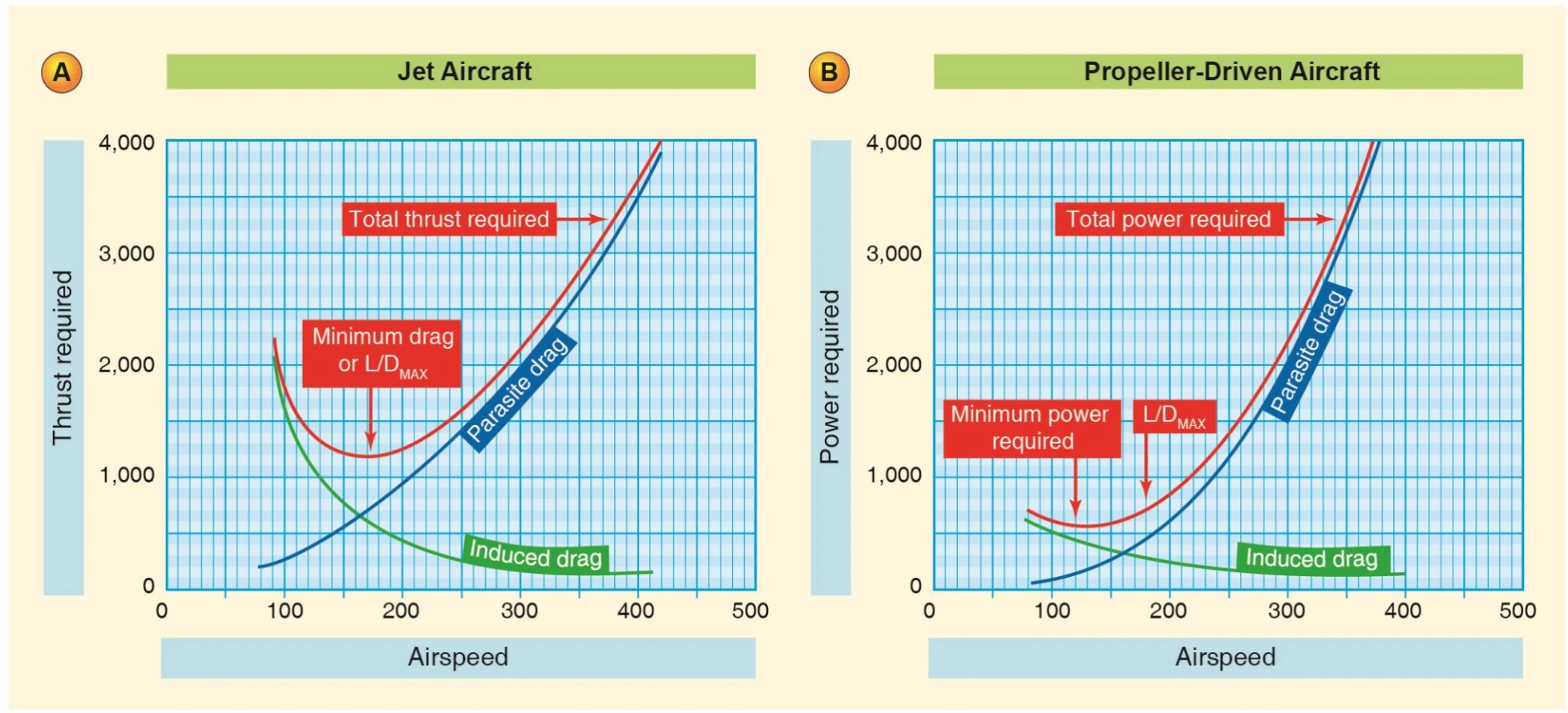
Stalls
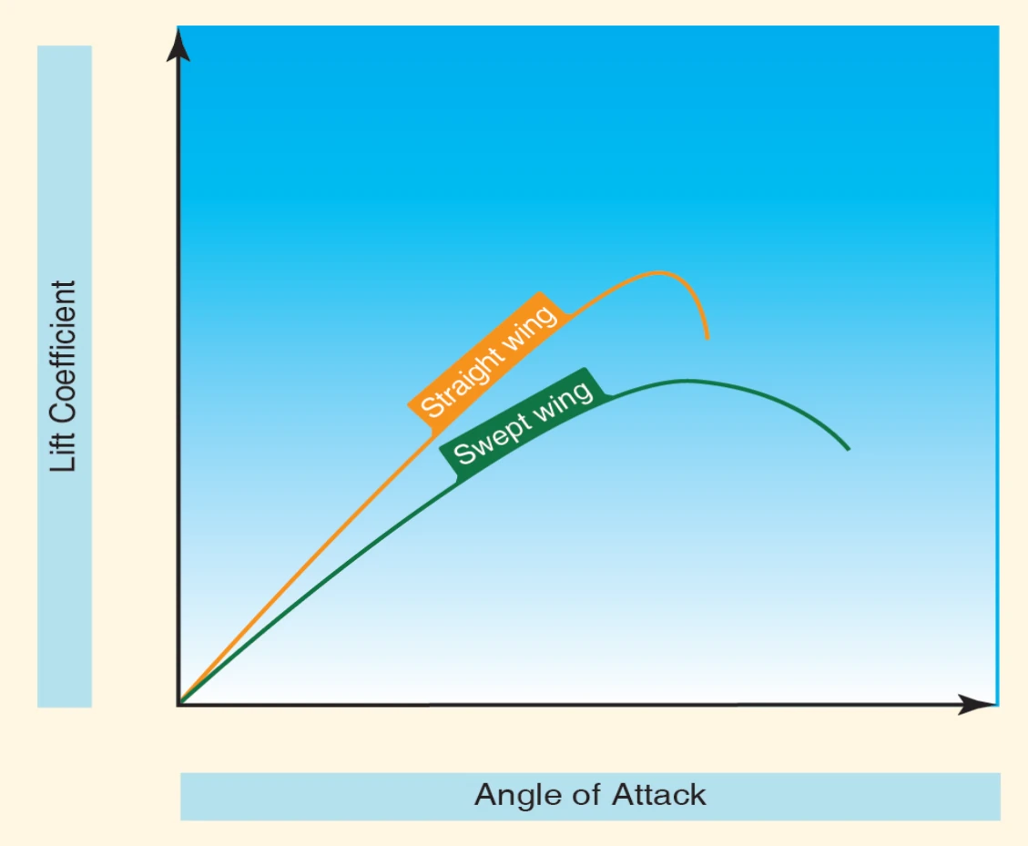
The stalling characteristics of the swept wing jet airplane can vary considerably from those of the normal straight wing airplane. The greatest difference noticeable to the pilot is the lift developed vs. angle of attack. An increase in angle of attack of the straight wing produces a substantial and constantly increasing lift vector up to its maximum coefficient of lift, and soon thereafter flow separation (stall) occurs with a rapid deterioration of lift.
By contrast, the swept wing produces a much more gradual buildup of lift with a less well-defined maximum coefficient. This less-defined peak also means that a swept wing may not have as dramatic a loss of lift at angles of attack beyond its maximum lift coefficient. However, these high-lift conditions are accompanied by high drag, which may result in a high rate of descent. [Figure 16-8]
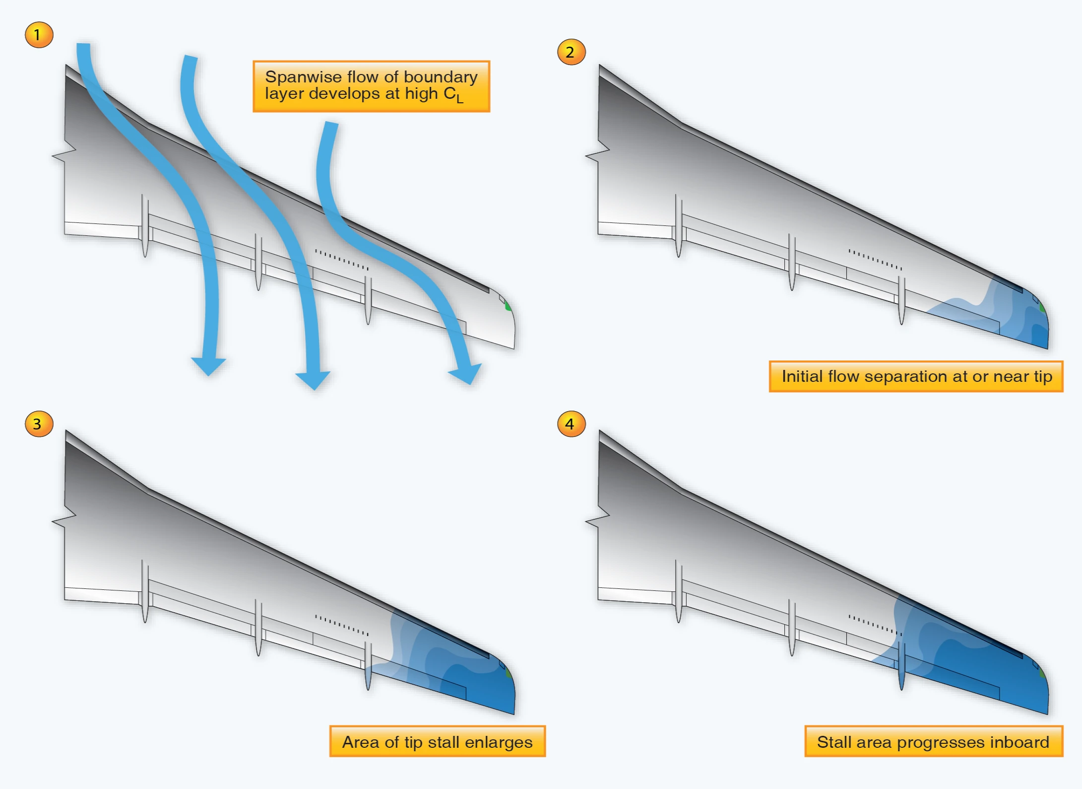
If a simple, straight-wing airplane’s airfoil is swept, a natural tendency arises that it will stall at the wing tips first. This is because the boundary layer tends to flow spanwise toward the tips. [Figure 16-9] The tendency for tip stall allowing the center of lift to move forward is greatest when wing sweep and taper are combined. To discourage a swept wing from stalling at the wingtips, manufacturers modify the wing spanwise with twist, changes in airfoil section, inclusion of vortex generators, or a combination of those modifications. This helps a pilot retain roll control initially if a stall is entered inadvertently.
Some T-tail configurations are prone to so-called deep stalls where the tail can become immersed in the wing wake at very high angles of attack and lose effectiveness. Such a situation can be accompanied by a high-rate of descent. Since high angles of attack can occur at any pitch attitude, even a pitch attitude with the nose below the horizon, it may seem counterintuitive in such a situation to take the appropriate recovery action, which is to push the nose down even further.
Deep stalls may be unrecoverable. Fortunately, they are easily avoided as long as published limitations are observed. On those airplanes susceptible to deep stalls (not all swept or tapered wing airplanes are), sophisticated stall warning systems such as stick shakers are standard equipment. A stick pusher (if installed), as its name implies, acts to automatically reduce the airplane’s AOA before the airplane reaches a dangerous stall condition, or it may aid in recovering the airplane from a stall if an airplane’s natural aerodynamic characteristics do so weakly. Pilots should avoid situations that would activate a stick pusher when close to the ground.
Pilots undergoing training in jet airplanes are taught to recover at the first indication of an impending stall instead of going beyond those initial cues and into a full stall. Normally, this is indicated by aural stall warning devices, annunciators, or activation of the airplane’s stick shaker. Stick shakers normally activate around 107 percent of the actual stall speed. In response to a stall warning, the proper action is for the pilot to apply a nose-down input until the stall warning stops (pitch trim may be necessary). Then, the wings are rolled level, followed by adjusting thrust to return to normal flight. The elapsed time will be small between these actions, particularly at low altitude where significant available thrust exists. It is important to understand that reducing AOA eliminates the stall, but added thrust will allow the descent to be stopped once the wing is flying again. Note that airplanes without vortex generators may stall with little to no buffet.
At high altitudes the stall recovery technique is the same. A pilot will need to reduce the AOA by lowering the nose until the stall warning stops. However, after the AOA has been reduced to where the wing is again developing efficient lift, the airplane will still likely need to accelerate to a desired airspeed. At high altitudes where the available thrust is significantly less than at lower altitudes, recovery may require significant pitch down to regain airspeed. As such, several thousand feet or more of altitude loss may occur during the recovery. The above discussion covers most airplanes; however, the stall recovery procedures for a particular make and model airplane may differ, as recommended by the manufacturer, and are contained in the FAA-approved Airplane Flight Manual for that airplane.
Drag Devices
Jet airplanes have higher glide ratios than piston-powered airplanes. Due to their low drag design, jets take more time and distance to descend or reduce speed. Therefore, jet airplanes are often equipped with drag devices, such as spoilers and speed brakes.
The primary purpose of spoilers is to spoil lift. The most common type of spoiler consists of one or more rectangular plates that lie flush with the upper surface of each wing. They are installed approximately parallel to the lateral axis of the airplane and are hinged along the leading edges. When deployed, spoilers deflect up against the relative wind, which interferes with the flow of air about the wing. [Figure 16-10] This both spoils lift and increases drag. Spoilers are usually installed forward of the flaps but not in front of the ailerons so as not to interfere with roll control. Some aircraft use spoilers to augment roll control.
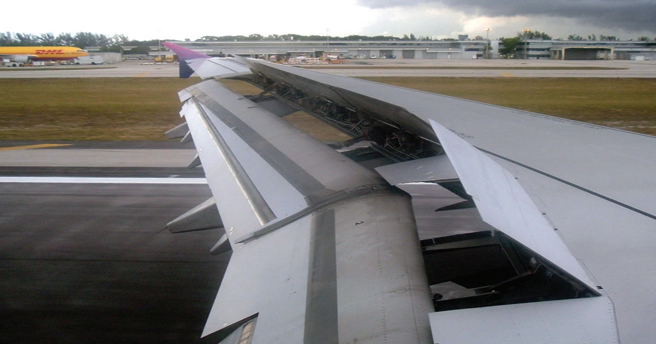
When flight and ground spoilers are deployed after landing, most of the wing’s lift is destroyed. This action transfers the airplane’s weight to the landing gear so that the wheel brakes are more effective. A secondary beneficial effect of deploying spoilers on landing is that they create considerable drag, adding to the overall aerodynamic braking.
The primary purpose of speed brakes is to produce drag. Spoilers may also serve as speed brakes, or they may be panels attached to the fuselage. Deploying speed brakes results in a rapid decrease in airspeed and/or an increased rate of descent. Typically, speed brakes can be deployed at any time during flight. There is usually a certain amount of noise and buffeting associated with the use of speed brakes, along with an obvious penalty in fuel consumption. Pilots can minimize the use of speed brakes with proper descent and approach planning. Procedures for the use of spoilers and/or speed brakes in various situations are contained in the FAA-approved AFM for the particular airplane.
Thrust Reversers
Jet airplanes have high kinetic energy during the landing roll because of weight and speed. This energy is difficult to dissipate because a jet airplane has low drag with the nose-wheel on the ground, and the engines continue to produce forward thrust with the power levers at idle. While wheel brakes serve as the primary means to stop the airplane, reverse thrust, when available, assists in deceleration.
Certain thrust reverser designs effectively reverse the flow of the exhaust gases. The flow does not completely reverse. Typically, the final path of the exhaust gases is about 45° from straight ahead. This, together with the losses from the flow paths, reduces reverse thrust efficiency. If the pilot uses less than maximum rpm in reverse, the reverse thrust is further reduced.