Chapter 13
Aircraft Landing Gear Systems
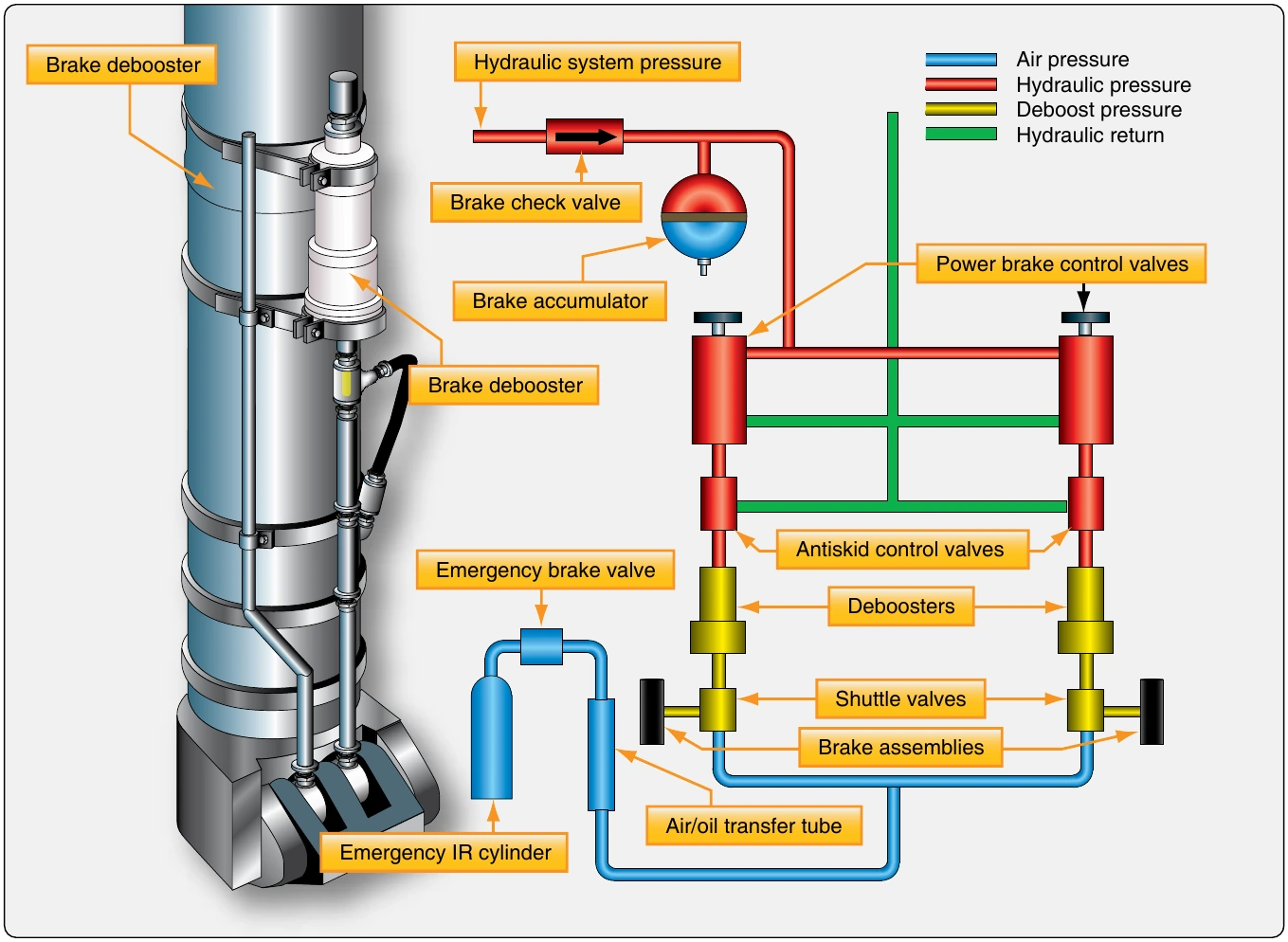
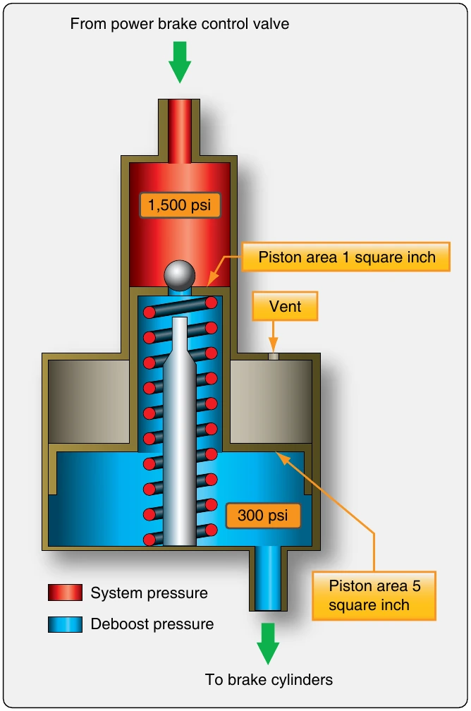
High-pressure hydraulic system input pressure acts on the small end of a piston. This develops a force proportional to the area of the piston head. The other end of the piston is larger and housed in a separate cylinder. The force from the smaller piston head is transferred to the larger area of the other end of the piston. The amount of pressure conveyed by the larger end of the piston is reduced due to the greater area over which the force is spread. The volume of output fluid increases since a larger piston and cylinder are used. The reduced pressure is delivered to the brake assembly.
The spring in the debooster aids in returning the piston to the ready position. If fluid is lost downstream of the deboost cylinder, the piston travels further down into the cylinder when the brakes are applied. The pin unseats the ball and allows fluid into the lower cylinder to replace what was lost. Once replenished, the piston rises up in the cylinder due to pressure build-up. The ball reseats as the piston travels above the pin and normal braking resumes. This function is not meant to permit leaks in the brake assemblies. Any leak discovered must be repaired by the technician.
A lockout debooster functions as a debooster and a hydraulic fuse. If fluid is not encountered as the piston moves down in the cylinder, the flow of fluid to the brakes is stopped. This prevents the loss of all system hydraulic fluid should a rupture downstream of the debooster occur. Lockout deboosters have a handle to reset the device after it closes as a fuse. If not reset, no braking action is possible.
Anti-Skid
Large aircraft with power brakes require anti-skid systems. It is not possible to immediately ascertain in the flight deck when a wheel stops rotating and begins to skid, especially in aircraft with multiple-wheel main landing gear assemblies. A skid not corrected can quickly lead to a tire blowout, possible damage to the aircraft, and control of the aircraft may be lost.
System Operation
The anti-skid system not only detects wheel skid, it also detects when wheel skid is imminent. It automatically relieves pressure to the brake pistons of the wheel in question by momentarily connecting the pressurized brake fluid area to the hydraulic system return line. This allows the wheel to rotate and avoid a skid. Lower pressure is then maintained to the brake at a level that slows the wheel without causing it to skid.
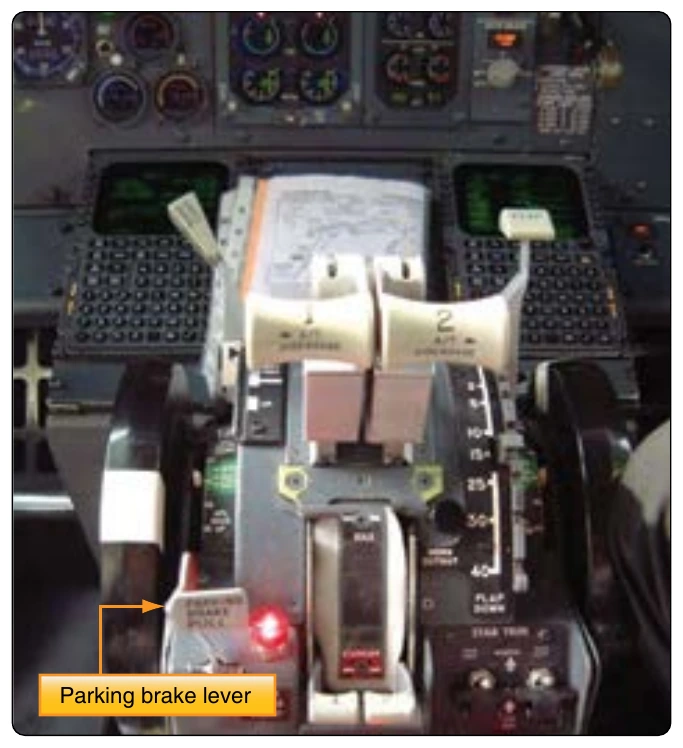
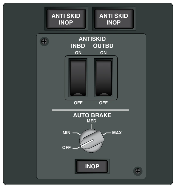
Maximum braking efficiency exists when the wheels are decelerating at a maximum rate but are not skidding. If a wheel decelerates too fast, it is an indication that the brakes are about to lock and cause a skid. To ensure that this does not happen, each wheel is monitored for a deceleration rate faster than a preset rate. When excessive deceleration is detected, hydraulic pressure is reduced to the brake on that wheel. To operate the anti-skid system, flight deck switches must be placed in the ON position. [Figure 13-106] After the aircraft touches down, the pilot applies and holds full pressure to the rudder brake pedals. The anti-skid system then functions automatically until the speed of the aircraft has dropped to approximately 20 mph. The system returns to manual braking mode for slow taxi and ground maneuvering.
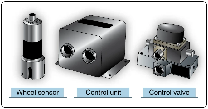
There are various designs of anti-skid systems. Most contain three main types of components: wheel speed sensors, anti-skid control valves, and a control unit. These units work together without human interference. Some anti-skid systems provide complete automatic braking. The pilot needs only to turn on the auto brake system, and the anti-skid components slow the aircraft without pedal input. [Figure 13-106] Ground safety switches are wired into the circuitry for anti-skid and auto brake systems. Wheel speed sensors are located on each wheel equipped with a brake assembly. Each brake also has its own anti-skid control valve. Typically, a single control box contains the anti-skid comparative circuitry for all of the brakes on the aircraft. [Figure 13-107]
Wheel Speed Sensors
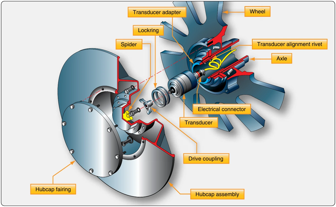
Wheel speed sensors are transducers. They may be alternating current (AC) or direct current (DC). The typical AC wheel speed sensor has a stator mounted in the wheel axle. A coil around it is connected to a controlled DC source so that when energized, the stator becomes an electromagnet. A rotor that turns inside the stator is connected to the rotating wheel hub assembly through a drive coupling so that it rotates at the speed of the wheel. Lobes on the rotor and stator cause the distance between the two components to constantly change during rotation. This alters the magnetic coupling or reluctance between the rotor and stator. As the electromagnetic field changes, a variable frequency AC is induced in the stator coil. The frequency is directly proportional to the speed of rotation of the wheel. The AC signal is fed to the control unit for processing. A DC wheel speed sensor is similar, except that a DC is produced the magnitude of which is directly proportional to wheel speed. [Figure 13-108]
Control Units
The control unit can be regarded as the brain of the anti-skid system. It receives signals from each of the wheel sensors. Comparative circuits are used to determine if any of the signals indicate a skid is imminent or occurring on a particular wheel. If so, a signal is sent to the control valve of the wheel to relieve hydraulic pressure to that brake which prevents or relieves the skid. The control unit may or may not have external test switches and status indicating lights. It is common for it to be located in the avionics bay of the aircraft. [Figure 13-109]
The Boeing anti-skid control valve block diagram in Figure 13-110 gives further detail on the functions of an anti-skid control unit. Other aircraft may have different logic to achieve similar end results. DC systems do not require an input converter since DC is received from the wheel sensors, and the control unit circuitry operates primarily with DC. Only the functions on one circuit card for one-wheel brake assembly are shown in Figure 13-110. Each wheel has its own identical circuitry card to facilitate simultaneous operation. All cards are housed in a single control unit that Boeing calls a control shield.