Chapter 14
Aircraft Fuel Systems
Boost pump access panel No. 2 by the technician. A full-time spotter must be positioned just outside of the tank to assist if needed.
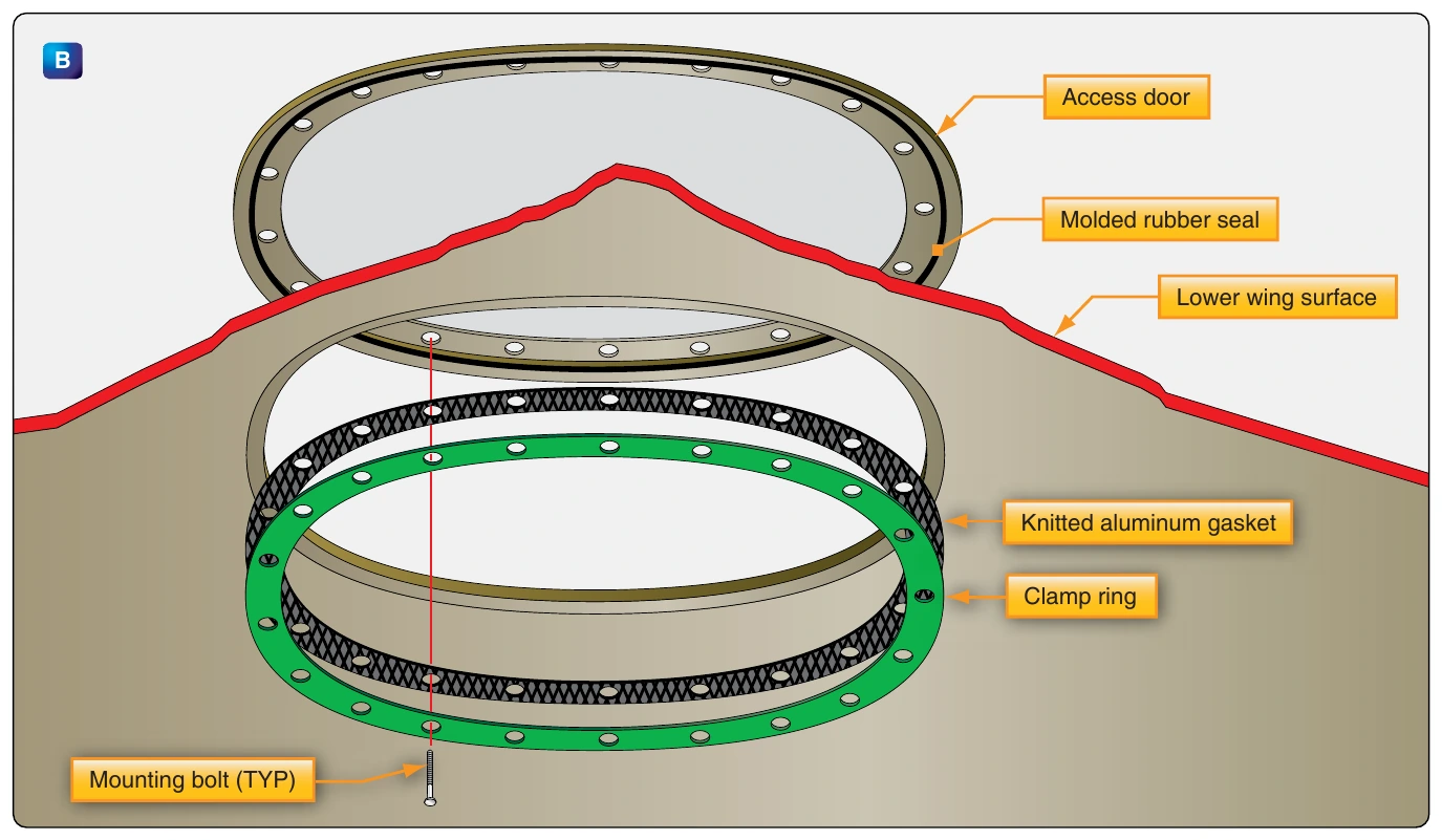
Aircraft using integral fuel tanks normally have sophisticated fuel systems that include in-tank boost pumps. There are usually at least two pumps in each tank that deliver fuel to the engine(s) under positive pressure. On various aircraft, these in-tank boost pumps are also used to transfer fuel to other tanks, jettison fuel, and defuel the aircraft.
Fuel Lines & Fittings
Aircraft fuel lines can be rigid or flexible depending on location and application. Rigid lines are often made of aluminum alloy and are connected with Army/Navy (AN) or military standard (MS) fittings. However, in the engine compartment, wheel wells, and other areas, subject to damage from debris, abrasion, and heat, stainless steel lines are often used.
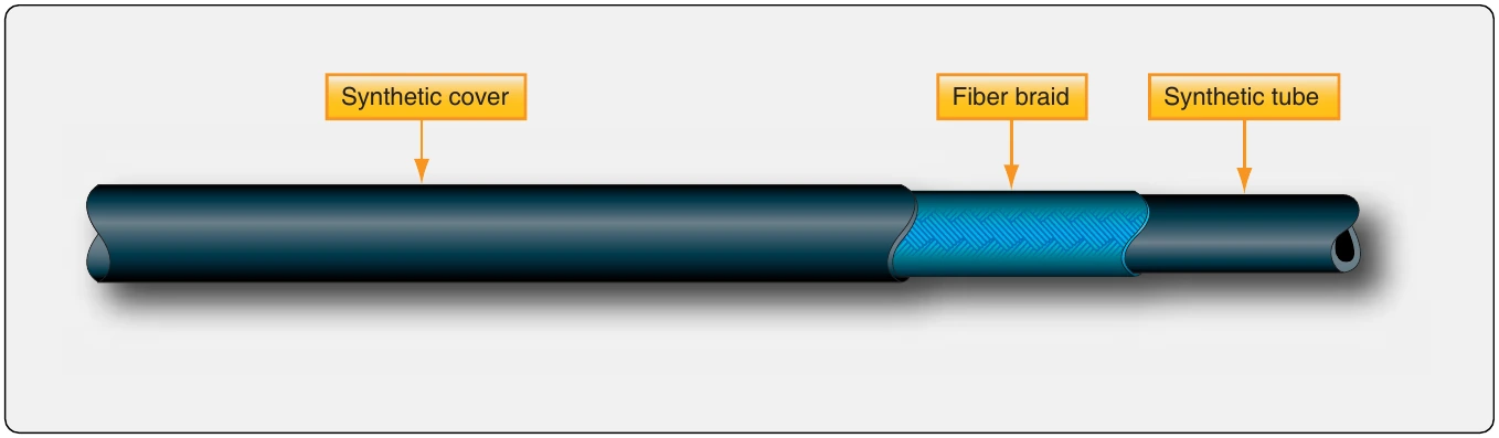
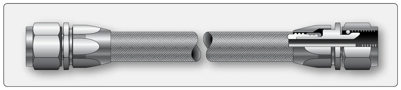
Flexible fuel hose has a synthetic rubber interior with a reinforcing fiber braid wrap covered by a synthetic exterior. [Figure 14-34] The hose is approved for fuel and no other hose should be substituted. Some flexible fuel hoses have a braided stainless steel exterior. [Figure 14-35] The diameters of all fuel hoses and lines are determined by the fuel flow requirements of the aircraft fuel system. Flexible hoses are used in areas where vibration exists between components, such as between the engine and the aircraft structure.
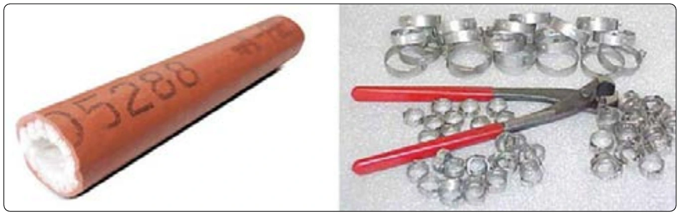
Sometimes manufacturers wrap either flexible or rigid fuel lines to provide even further protection from abrasion and especially from fire. A fire sleeve cover is held over the line with steel clamps at the end fittings. [Figure 14-36]
As mentioned, aircraft fuel line fittings are usually either AN or MS fittings. Both flared and flareless fittings are used. Problems with leaks at fittings can occur. Technicians are cautioned to not overtighten a leaky fitting. If the proper torque does not stop a leak, depressurize the line, disconnect the fitting and visually inspect it for a cause. The fitting or line should be replaced if needed. Replace all aircraft fuel lines and fittings with approved replacement parts from the manufacturer. If a line is manufactured in the shop, approved components must be used.
Several installation procedures for fuel hoses and rigid fuel lines exist. Hoses should be installed without twisting. The writing printed on the outside of the hose is used as a lay line to monitor fuel hose twist. Separation should be maintained between all fuel hoses and electrical wiring. Never clamp wires to a fuel line. When separation is not possible, always route the fuel line below any wiring. If a fuel leak develops, it does not drip onto the wires.
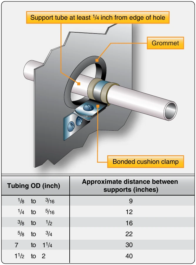
Metal fuel lines and all aircraft fuel system components need to be electrically bonded and grounded to the aircraft structure. This is important because fuel flowing through the fuel system generates static electricity that must have a place to flow to ground rather than build up. Special bonded cushion clamps are used to secure rigid fuel lines in place. They are supported at intervals shown in Figure 14-37.
All fuel lines should be supported so that there is no strain on the fittings. Clamp lines so that fittings are aligned. Never draw two fittings together by threading. They should thread easily, and a wrench should be used only for tightening. Additionally, a straight length of rigid fuel line should not be made between two components or fittings rigidly mounted to the airframe. A small bend is needed to absorb any strain from vibration or expansion and contraction due to temperature changes.
Fuel Valves
There are many fuel valve uses in aircraft fuel systems. They are used to shut off fuel flow or to route the fuel to a desired location. Other than sump drain valves, light aircraft fuel systems may include only one valve, the selector valve. It incorporates the shutoff and selection features into a single valve. Large aircraft fuel systems have numerous valves. Most simply open and close and are known by different names related to their location and function in the fuel system (e.g., shutoff valve, transfer valve, crossfeed valve). Fuel valves can be manually operated, solenoid operated, or operated by electric motor.
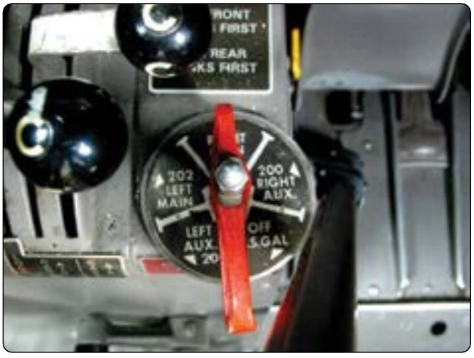
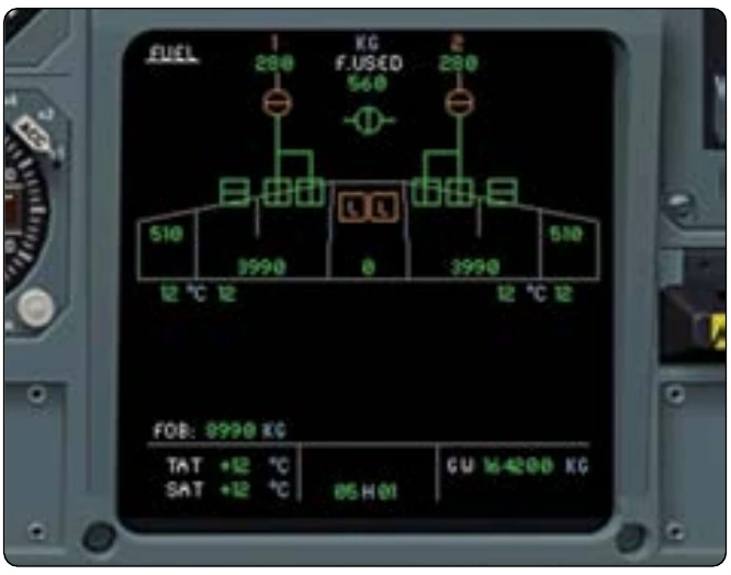
A feature of all aircraft fuel valves is a means for positively identifying the position of the valve at all times. Hand-operated valves accomplish this through the use of detents into which a spring-loaded pin or similar protrusion locates when the valve is set in each position. Combined with labels and a directional handle, this makes it easy to identify by feel and by sight that the valve is in the desired position. [Figure 14-38] Motor- and solenoid-operated valves use position annunciator lights to indicate valve position in addition to the switch position. Flight management system (FMS) fuel pages also display the position of the fuel valves graphically in diagrams called up on the flat screen monitors. [Figure 14-39] Many valves have an exterior position handle, or lever, that indicates valve position. When maintenance personnel directly observe the valve, it can be manually positioned by the technician using this same lever. [Figure 14-40]