
Chapter 14
Aircraft Fuel Systems
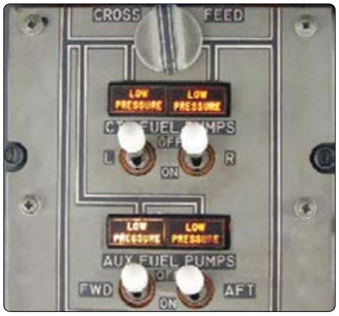
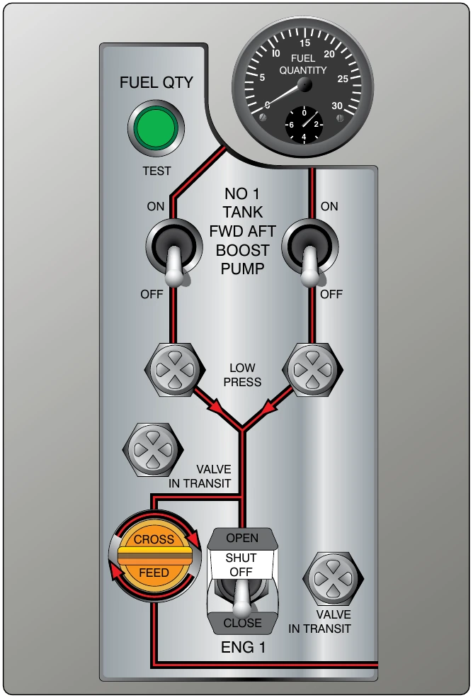
Some aircraft indicate to the crew when the valve is opening or closing with the use of valve-in-transit lights. Contacts in the valve control the lights that go out when the valve is fully open or when it is fully closed. Alternately, annunciator lights that show the valve position as OPEN or CLOSED are also used. Valve-in-transit and valve position indicators, or lights, are located on the fuel panel in the flight deck adjacent to the valve ON/OFF switches. [Figure 14-88] Sometimes the switch mechanism has the annunciator light built into it. Digital display systems graphically depict valve positions on screen.
Fuel System Repair
The integrity of an aircraft fuel system is critical and should not be compromised. Any evidence of malfunction or leak should be addressed before the aircraft is released for flight. The danger of fire, explosion, or fuel starvation in flight makes it imperative that fuel system irregularities be given top priority. Each manufacturer’s maintenance and operation instructions must be used to guide the technician in maintaining the fuel system in airworthy condition. Follow the manufacturer’s instructions at all times. Component manufacturers and STC holder instructions should be used when applicable. Some general instructions for fuel system maintenance and repair are given in the following sections.
Troubleshooting the Fuel System
Knowledge of the fuel system and how it operates is essential when troubleshooting. Manufacturers produce diagrams and descriptions in their maintenance manuals to aid the technician. Study these for insight. Many manuals have troubleshooting charts or flow diagrams that can be followed. As with all troubleshooting, a logical sequence of steps to narrow the problem to a specific component or location should be followed. Defects within the system can often be located by tracing the fuel flow from the tank through the system to the engine. Each component must be functioning as designed and the cause of the defect symptom must be ruled out sequentially.
Location of Leaks & Defects
Close visual inspection is required whenever a leak or defect is suspected in a fuel system. Leaks can often be traced to the connection point of two fuel lines or a fuel line and a component. Occasionally, the component itself may have an internal leak. Fuel leaks also occur in fuel tanks and are discussed below. Leaking fuel produces a mark where it travels. It can also cause a stronger than normal odor. Gasoline may collect enough of its dye for it to be visible or an area clean of dirt may form. Jet fuel is difficult to detect at first, but it has a slow evaporation rate. Dirt and dust eventually settle into it, which makes it more visible.
When fuel leaks into an area where the vapors can collect, the leak must be repaired before flight due to the potential for fire or explosion. Repair could be deferred for external leaks that are not in danger of being ignited. However, the source of the leak should be determined and monitored to ensure it does not become worse. Follow the aircraft manufacturer’s instructions on the repair of fuel leaks and the requirements that need to be met for airworthiness. Detailed visual inspection can often reveal a defect.
Fuel Leak Classification
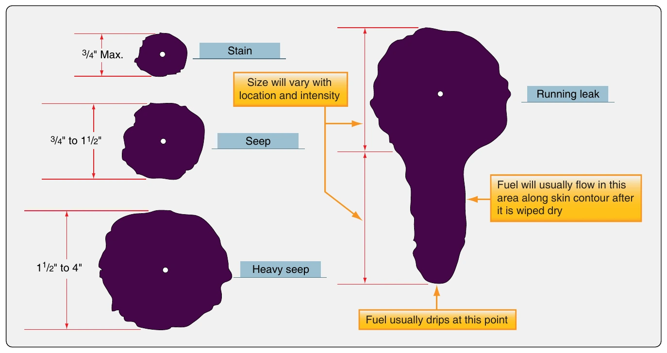
Four basic classifications are used to describe aircraft fuel leaks: stain, seep, heavy seep, and running leak. [Figure 14-89] In 30 minutes, the surface area of the collected fuel from a leak is a certain size. This is used as the classification standard. When the area is less than ¾ inch in diameter, the leak is said to be a stain. From ¾ to 1½ inches in diameter, the leak is classified as a seep. Heavy seeps form an area from 1½ inches to 4 inches in diameter. Running leaks pool and actually drip from the aircraft. They may follow the contour of the aircraft for a long distance.
Replacement of Gaskets, Seals, & Packings
A leak can often be repaired by replacing a gasket or seal. When this occurs, or a component is replaced or reassembled after a maintenance operation, a new gasket, seal, or packing must be installed. Do not use the old one(s). Always be sure to use the correct replacement as identified by part number. Also, most gaskets, seals, and packings have a limited shelf life. They should be used only if they are within the service life stamped on the package.
Remove the entire old gasket completely and clean all mating surfaces. Clean surfaces and grooves allow a tight seal. Inspect new gaskets and seals for any flaws. Follow the manufacturer’s instructions for replacement, including cleaning procedures and any sealing compound that you may need to apply during replacement. Torque assembly bolts evenly so as to provide even pressure and prevent pinching.
Fuel Tank Repair
Whether rigid removable, bladder-type, or integral, all fuel tanks have the potential to develop leaks. Repair a tank according to the manufacturer’s instructions. Some general notes for repair of each tank type follow. At the time a tank is repaired, a thorough inspection should be made. Corrosion, such as that caused by water and microbes, should be identified and treated at this time, even if it is not the cause of the leak.
Rigid removable fuel tanks can be riveted, welded, or soldered together. A leak can develop at any of these types of seams or can be elsewhere on the tank. Generally, the repair must match the construction in technique.
Some metal fuel tanks experiencing minor seepage can be repaired with a sloshing procedure. An approved sloshing compound is poured into the tank, and the tank is moved so that the compound coats the entire inner surface area of the tank. Any excess compound is then poured out and the compound in the tank is allowed to cure for a specified amount of time. Minor gaps in the seams of the tank and repairs are filled in this manner. The compound is fuel resistant once dry. Check with the aircraft manufacturer to ensure that sloshing is an airworthy repair for the aircraft fuel tank in question.