Chapter 15
Ice & Rain Protection
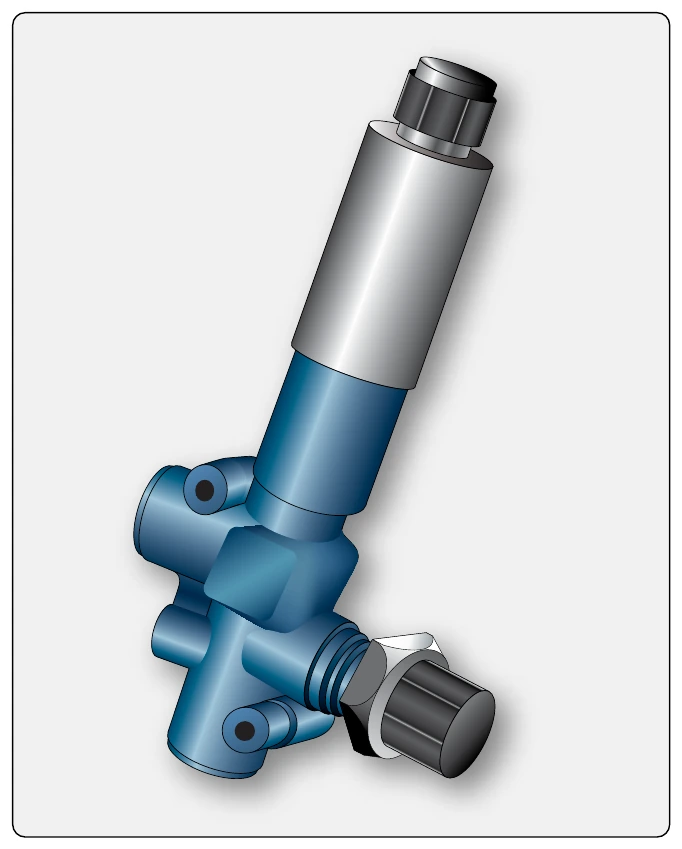
Another type of distributor valve exists that handles the inflation and deflation of numerous sets of deice boots in a single unit. It also connects the boots to vacuum and dumps pump air when deice is not needed. A servo motor is used to position the multi-position valve. These centralized units are controlled by a timer or control unit. They inflate and deflate all of the boots on the aircraft. The timer may be built into the unit on some models.
Timer/Control Unit
All but the simplest of deice systems contain a timer or control unit. This device controls the action of the distributor valve(s) to ensure all boots are inflated in the proper sequence and for the correct duration. Six seconds of inflation is common to break off accumulated ice. The boot then must be immediately deflated so that ice does not adhere to the inflated geometry of the boot. This could cause it to fail to deflate or break off ice when the boot is re-inflated. The timer, or control unit, can also be made to cycle through the inflation and deflation of all boots periodically, thus relieving the flight crew of repetitive manual activation of the system. The function and capabilities of timers and control units vary. Consult the manufacturer’s maintenance information for the performance characteristics of the timer/control unit on the aircraft in question.
The timer, or control unit, may be an independent device, or it may be built-in as part of another deice system component, such as a central distribution valve.
Regulators & Relief Valves
Both the pressure and vacuum developed by an air pump must be regulated for use in the deice boot system. Typical boot inflation air pressure is between 15 and 20 psi. Vacuum pressure is set for the requirements of the gyroscopic instruments operated by the vacuum side of the air pump. Measured in inches of mercury, normal vacuum pressure (suction) is 4.5 to 5.5 "Hg.
Deice boot system air pressure is controlled by a pressure regulator valve located somewhere in the system downstream of the pump or oil separator, if installed. The regulator may be a stand-alone unit, or it may be combined into another deice system component. Regardless, the spring-loaded valve relieves pressure overboard when it exceeds the limit for which the system is designed.
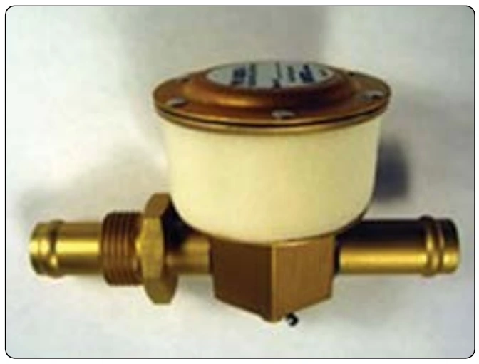
A vacuum regulator is installed in the vacuum manifold on the suction side of the air pump to maintain the vacuum at the designed level. Also known as a suction regulating valve or similar, the spring-loaded valve contains a filter for the ambient air drawn through the valve during operation. This filter must be changed or kept clean per manufacturer’s instructions. [Figure 15-27]
Manifold Assembly
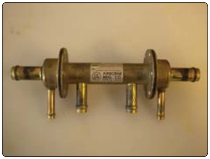
In all pneumatic deice boot systems, it is necessary for check valves to be installed to prevent backflow of air in the system. The location(s) depends on system design. Sometimes, the check valve is built into another system component. On twin-engine aircraft, it is common to unite the air supplied from each engine-driven pump to provide redundancy. Check valves are required to guard against backflow should one pump fail. A manifold assemble is commonly used to join both sides of the system. [Figure 15-28] It contains the required check valves in a single assembly.
Inlet Filter
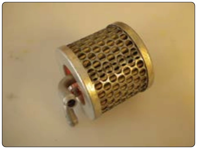
The air used in a deice boot system is ambient air drawn in upstream of the gyroscopic instruments on the suction side of the engine-driven air pump. This air must be free of contaminants for use spinning the gyros, as well as for inflation of the deice boots. To ensure clean air, an inlet filter is installed as the air intake point for the system. This filter must be regularly maintained as per manufacturer’s instructions. Figure 15-29 shows a typical inlet air filter. Figure 15-30 shows the relationship of the vacuum regulator and inlet air filter to other system components.
Construction & Installation of Deice Boots
Deicer boots are made of soft, pliable rubber, or rubberized fabric, and contain tubular air cells. The outer ply of the deicer boot is of conductive neoprene to provide resistance to deterioration by the elements and many chemicals. The neoprene also provides a conductive surface to dissipate static electricity charges. These charges, if allowed to accumulate, would eventually discharge through the boot to the metal skin beneath, causing static interference with the radio equipment. [Figure 15-31]
On modern aircraft, the deicer boots are bonded with an adhesive to the leading edge of wing and tail surfaces. The trailing edges of this type boot are tapered to provide a smooth airfoil. Elimination of fairing strips, screws, and rivnuts used on older types of deicing boots reduces the weight of the deice system. The deicer boot air cells are connected to system pressure and vacuum lines by non-kinking flexible hose.