
Chapter 15
Ice & Rain Protection
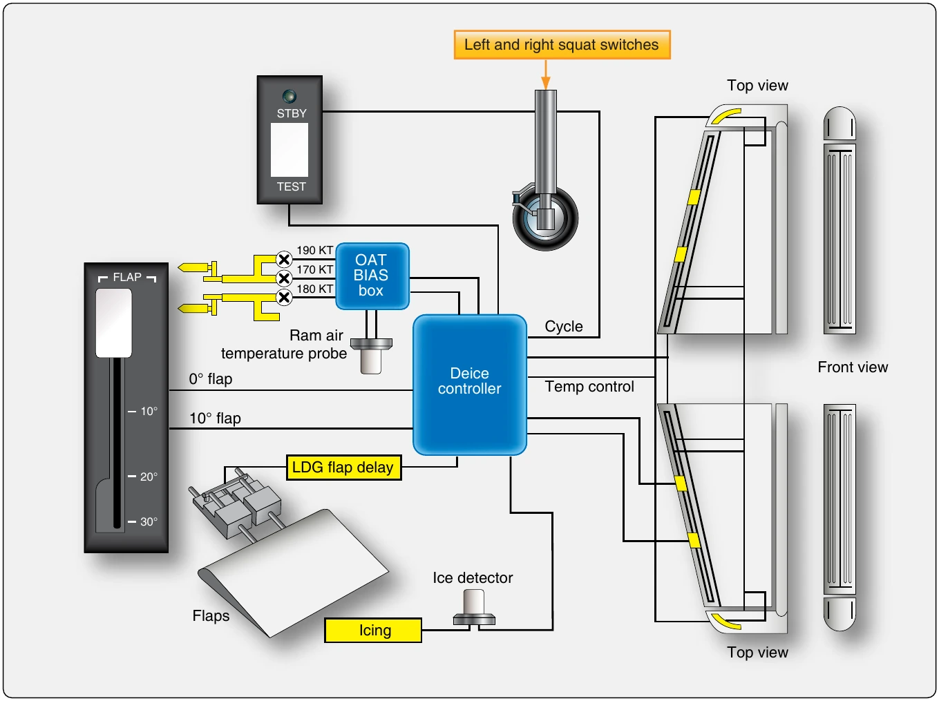
A few modern aircraft are equipped with electric deice boots on wing sections or on the horizontal stabilizer. These boots contain electric heating elements which are bonded to the leading edges similarly to pneumatic deice boots. When activated, the boots heat up and melt the ice off of leading edge surfaces. The elements are controlled by a sequence timer in a deice controller. Ice detector and ram air temperature probe inputs initiate operation when other flight condition parameters exist. The boot elements turn ON and OFF in paired sections to avoid aerodynamic imbalance. The system is inoperative while the aircraft is on the ground. Figure 15-34 illustrated such a system. A benefit of electric deice boots is the conservation of engine bleed air. Current draw is limited to only those periods when de-ice is required.
Propeller Deice System
The formation of ice on the propeller leading edges, cuffs, and spinner reduces the efficiency of the powerplant system. Deice systems using electrical heating elements and systems using chemical deicing fluid are used.
Electrothermal Propeller Device System
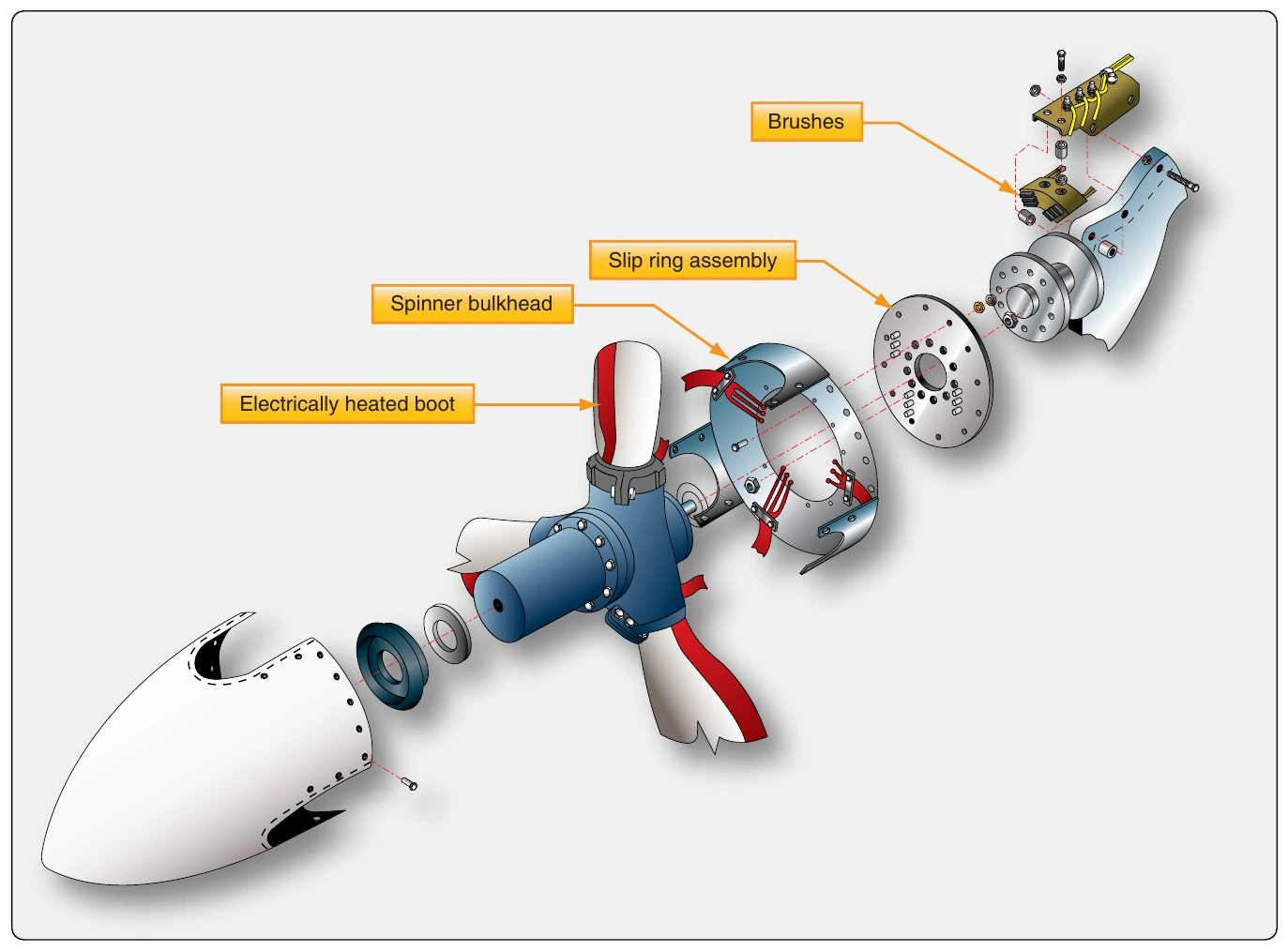
Many propellers are deiced by an electrically heated boot on each blade. The boot, firmly cemented in place, receives current from a slip ring and brush assembly on the spinner bulkhead. The slip ring transmits current to the deice boot. The centrifugal force of the spinning propeller and air blast breaks the ice particles loose from the heated blades. [Figure 15-35]
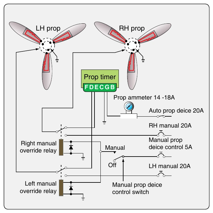
On one aircraft model, the boots are heated in a preset sequence, which is an automatic function controlled by a timer. This sequence is as follows: 30 seconds for the right prop outer elements; 30 seconds for the right prop inner elements; 30 seconds for the left prop outer elements; and, 30 seconds for the left prop inner elements. Once the system is turned on for automatic is activated, it cycles continuously. A manual bypass of the timer is incorporated. [Figure 15-36]
Chemical Propeller Deice
Some aircraft models, especially single-engine GA aircraft, use a chemical deicing system for the propellers. Ice usually appears on the propeller before it forms on the wing. The glycol-based fluid is metered from a tank by a small electrically driven pump through a microfilter to the slinger rings on the prop hub. The propeller system can be a stand-alone system, or it can be part of a chemical wing and stabilizer deicing system such as the TKS™ weeping system.
Ground Deicing of Aircraft
The presence of ice on an aircraft may be the result of direct precipitation, formation of frost on integral fuel tanks after prolonged flight at high altitude, or accumulations on the landing gear following taxiing through snow or slush. In accordance with the Federal Aviation Administration (FAA) Advisory Circular (AC) 120-60, the aircraft must be free of all frozen contaminants adhering to the wings, control surfaces, propellers, engine inlets, or other critical surfaces before takeoff.
Any deposits of ice, snow, or frost on the external surfaces of an aircraft may drastically affect its performance. This may be due to reduced aerodynamic lift and increased aerodynamic drag resulting from the disturbed airflow over the airfoil surfaces, or it may be due to the weight of the deposit over the whole aircraft. The operation of an aircraft may also be seriously affected by the freezing of moisture in controls, hinges, valves, microswitches, or by the ingestion of ice into the engine. When aircraft are hangared to melt snow or frost, any melted snow or ice may freeze again if the aircraft is subsequently moved into subzero temperatures. Any measures taken to remove frozen deposits while the aircraft is on the ground must also prevent the possible refreezing of the liquid.
Frost Removal
Frost deposits can be removed by placing the aircraft in a warm hangar or by using a frost remover or deicing fluid. These fluids normally contain ethylene glycol and isopropyl alcohol and can be applied either by spray or by hand. It should be applied within 2 hours of flight. Deicing fluids may adversely affect windows or the exterior finish of the aircraft, only the type of fluid recommended by the aircraft manufacturer should be used. Transport category aircraft are often deiced on the ramp or a dedicated deicing location at the airport. Deicing trucks are used to spray the deicing and/or anti-icing fluid on aircraft surfaces. [Figure 15-37]
Deicing & Anti-icing of Transport Type Aircraft
Deicing Fluid
The deicing fluid must be accepted according to its type for holdover times, aerodynamic performance, and material compatibility. The coloring of these fluids is also standardized. In general, glycol is colorless, Type-I fluids are orange, Type-II fluids are white/pale yellow, and Type- IV fluids are green. The color for Type-III fluid has not yet been determined.
When aircraft surfaces are contaminated by frozen moisture, they must be deiced prior to dispatch. When freezing precipitation exists, and there is a risk of contamination of the surface at the time of dispatch, aircraft surfaces must be anti-iced. If both deicing and anti-icing are required, the procedure may be performed in one or two steps. The selection of a one- or two-step process depends upon weather conditions, available equipment, available fluids, and the holdover time to be achieved.