
Chapter 16
Cabin Environmental Control Systems
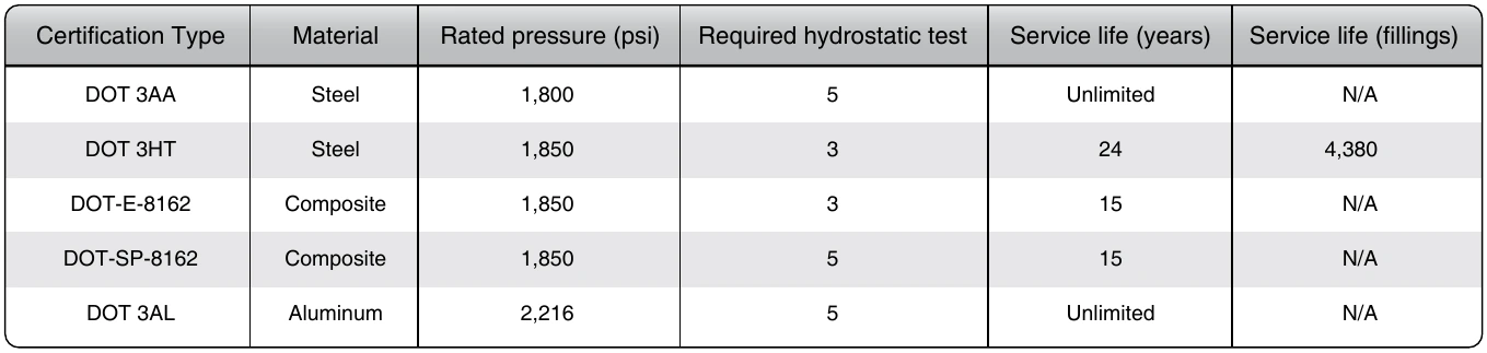
The manufactured date and certification number is stamped on each cylinder near the neck. Subsequent hydrostatic test dates are also stamped there as well. Composite cylinders use placards rather than stamping. The placard must be covered with a coat of clear epoxy when additional information is added, such as a new hydrostatic test date.
Oxygen cylinders are considered empty when the pressure inside drops below 50 psi. This ensures that air containing water vapor has not entered the cylinder. Water vapor could cause corrosion inside the tank, as well as presenting the possibility of ice forming and clogging a narrow passageway in the cylinder valve or oxygen system. Any installed tank allowed to fall below this pressure should be removed from service.
Oxygen Systems & Regulators
The design of the various oxygen systems used in aircraft depends largely on the type of aircraft, its operational requirements, and whether the aircraft has a pressurization system. Systems are often characterized by the type of regulator used to dispense the oxygen: continuous-flow and demand flow. In some aircraft, a continuous-flow oxygen system is installed for both passengers and crew. The pressure demand system is widely used as a crew system, especially on the larger transport aircraft. Many aircraft have a combination of both systems that may be augmented by portable equipment.
Continuous-Flow Systems
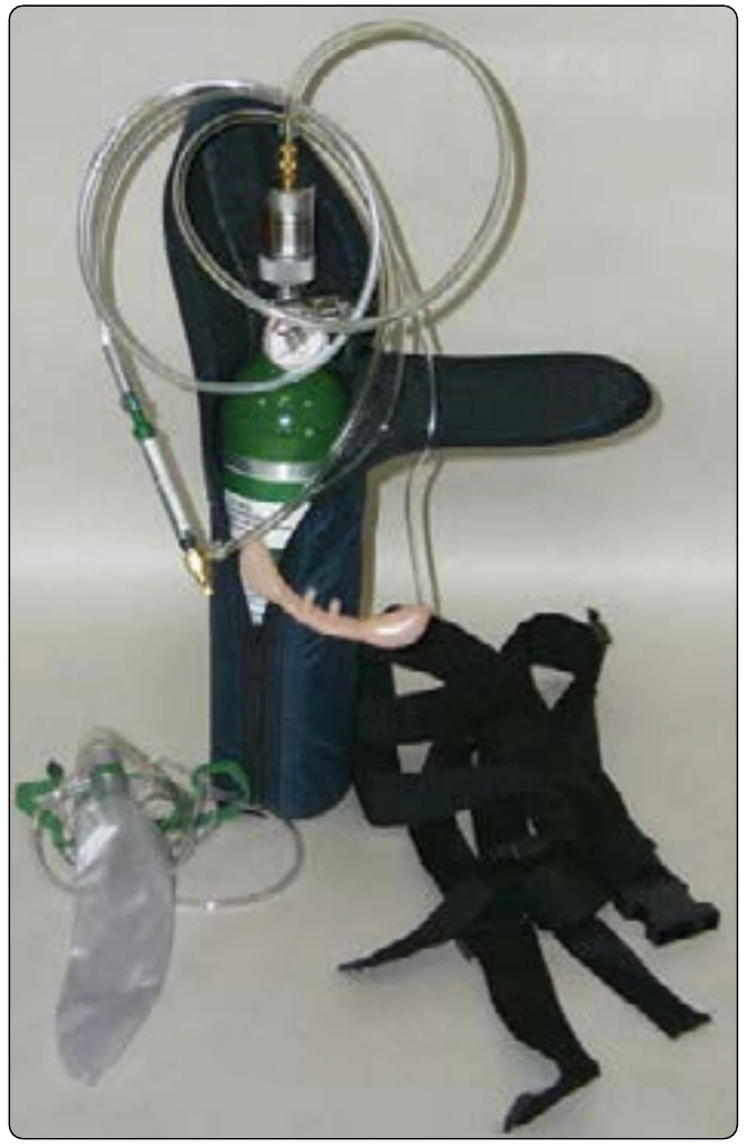
In its simplest form, a continuous-flow oxygen system allows oxygen to exit the storage tank through a valve and passes it through a regulator/reducer attached to the top of the tank. The flow of high-pressure oxygen passes through a section of the regulator that reduces the pressure of the oxygen, which is then fed into a hose attached to a mask worn by the user. Once the valve is opened, the flow of oxygen is continuous. Even when the user is exhaling, or when the mask is not in use, a preset flow of oxygen continues until the tank valve is closed. On some systems, fine adjustment to the flow can be made with an adjustable flow indicator that is installed in the hose in line to the mask. A portable oxygen setup for a light aircraft exemplifies this type of continuous-flow system and is shown in Figure 16-11.
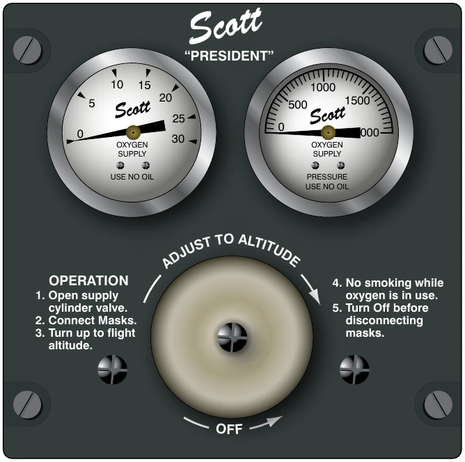
A more sophisticated continuous-flow oxygen system uses a regulator that is adjustable to provide varying amounts of oxygen flow to match increasing need as altitude increases. These regulators can be manual or automatic in design. Manual continuous-flow regulators are adjusted by the crew as altitude changes. Automatic continuous-flow regulators have a built in aneroid. As the aneroid expands with altitude, a mechanism allows more oxygen to flow though the regulator to the users. [Figure 16-12]
Many continuous-flow systems include a fixed location for the oxygen cylinders with permanent delivery plumbing installed to all passenger and crew stations in the cabin.
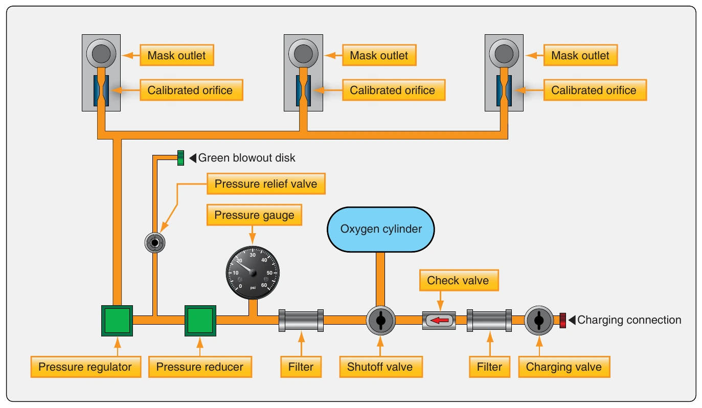
In large aircraft, separate storage cylinders for crew and passengers are typical. Fully integrated oxygen systems usually have separate, remotely mounted components to reduce pressure and regulate flow. A pressure relief valve is also typically installed in the system, as is some sort of filter and a gauge to indicate the amount of oxygen pressure remaining in the storage cylinder(s). Figure 16-13 diagrams the type of continuous-flow system that is found on small to medium sized aircraft.
Built-in continuous-flow gaseous oxygen systems accomplish a final flow rate to individual user stations through the use of a calibrated orifice in each mask. Larger diameter orifices are usually used in crew masks to provide greater flow than that for passengers. Special oxygen masks provide even greater flow via larger orifices for passengers traveling with medical conditions requiring full saturation of the blood with oxygen.
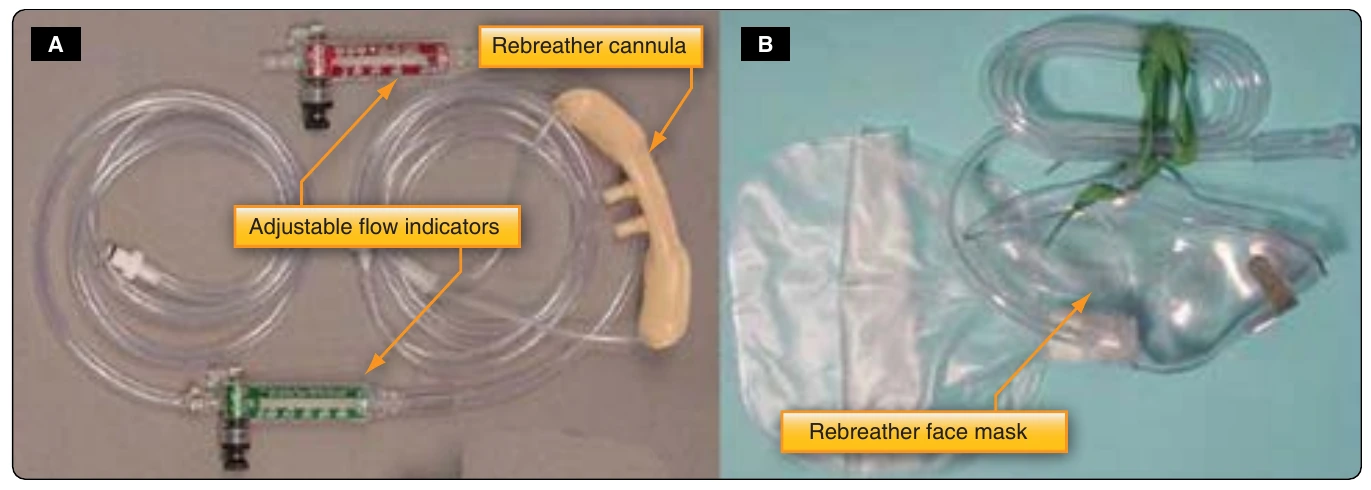
Allowing oxygen to continuously flow from the storage cylinder can be wasteful. Lowest sufficient flow rates can be accomplished through the use of rebreather apparatus. Oxygen and air that is exhaled still contains usable oxygen. By capturing this oxygen in a bag, or in a cannula with oxygen absorbing reservoirs, it can be inhaled with the next breath, reducing waste. [Figure 16-14]
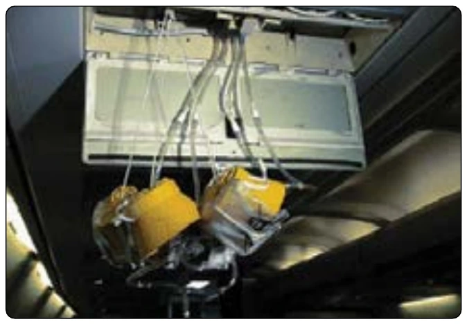
The passenger section of a continuous-flow oxygen system may consist of a series of plug-in supply sockets fitted to the cabin walls adjacent to the passenger seats to which oxygen masks can be connected. Flow is inhibited until a passenger manually plugs in. When used as an emergency system in pressurized aircraft, depressurization automatically triggers the deployment of oxygen ready continuous-flow masks at each passenger station. A lanyard attached to the mask turns on the flow to each mask when it is pulled toward the passenger for use. The masks are normally stowed overhead in the passenger service unit (PSU). [Figure 16-15] Deployment of the emergency continuous-flow passenger oxygen masks may also be controlled by the crew. [Figure 16-16] Continuous-flow oxygen masks are simple devices made to direct flow to the nose and mouth of the wearer. They fit snugly but are not air tight. Vent holes allow cabin air to mix with the oxygen and provide escape for exhalation. In a rebreather mask, the vents allow the exhaled mixture that is not trapped in the rebreather bag to escape. This is appropriate, because this is the air-oxygen mixture that has been in the lungs the longest, so it has less recoverable oxygen to be breathed again. [Figure 16-17]
Demand-Flow or Pressure-Demand Systems
When oxygen is delivered only as the user inhales, or on demand, it is known as a demand-flow system or a pressure-demand system. During the hold and exhalation periods of breathing, the oxygen supply is stopped. Thus, the duration of the oxygen supply is prolonged as none is wasted. Demand-flow systems are used most frequently by the crew on high performance and air transport category aircraft. [Figure 16-18]