
Chapter 16
Cabin Environmental Control Systems
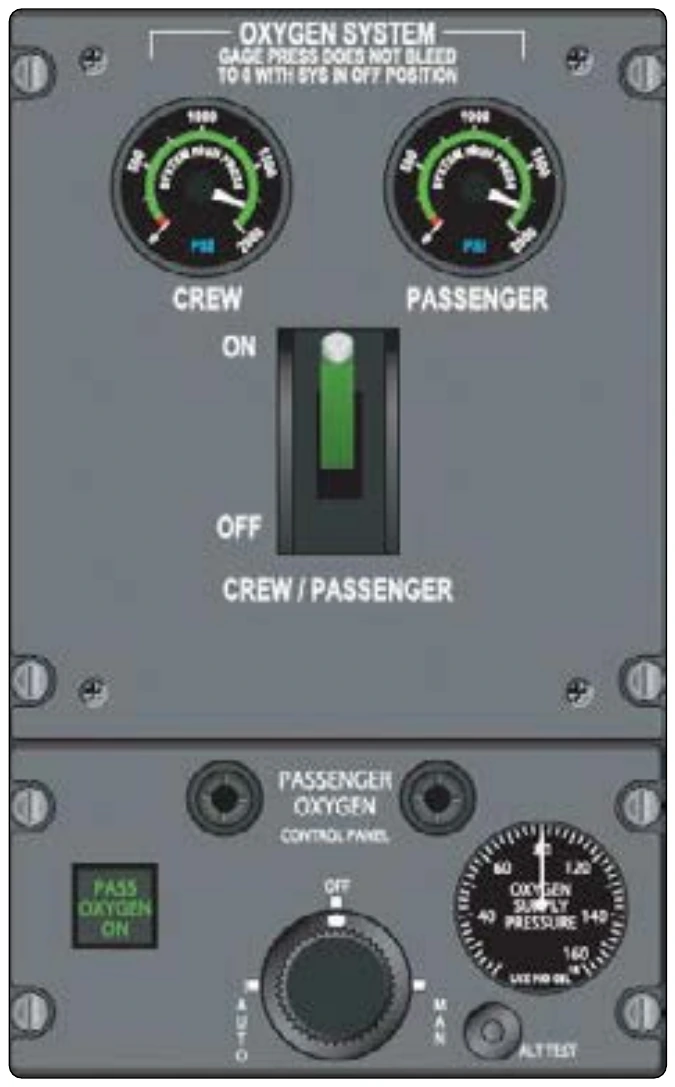
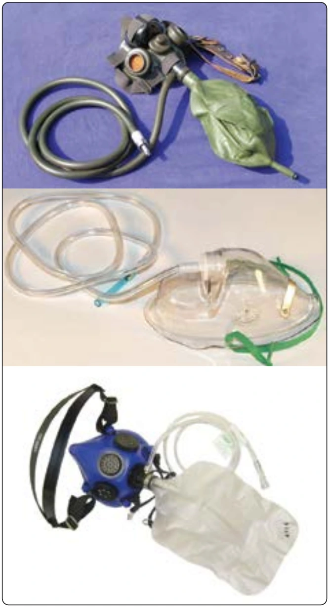
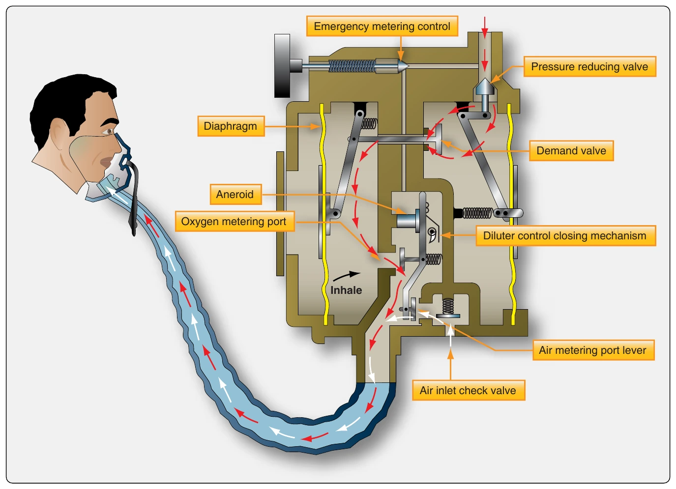
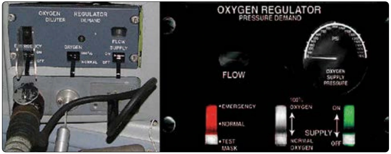
Demand-flow systems are similar to continuous-flow systems in that a cylinder delivers oxygen through a valve when opened. The tank pressure gauge, filter(s), pressure relief valve, and any plumbing installed to refill the cylinder while installed on the aircraft are all similar to those in a continuous-flow system. The high-pressure oxygen also passes through a pressure reducer and a regulator to adjust the pressure and flow to the user. But, demand-flow oxygen regulators differ significantly from continuous-flow oxygen regulators. They work in conjunction with close-fitting demand-type masks to control the flow of oxygen. [Figure 16-19] In a demand-flow oxygen system, the system pressure-reducing valve is sometimes called a pressure regulator. This device lowers the oxygen pressure from the storage cylinder(s) to roughly 60–85 psi and delivers it to individual regulators dedicated for each user. A pressure reduction also occurs at the inlet of the individual regulator by limiting the size of the inlet orifice. There are two types of individual regulators: the diluter-demand type and the pressure-demand type. [Figure 16-20]
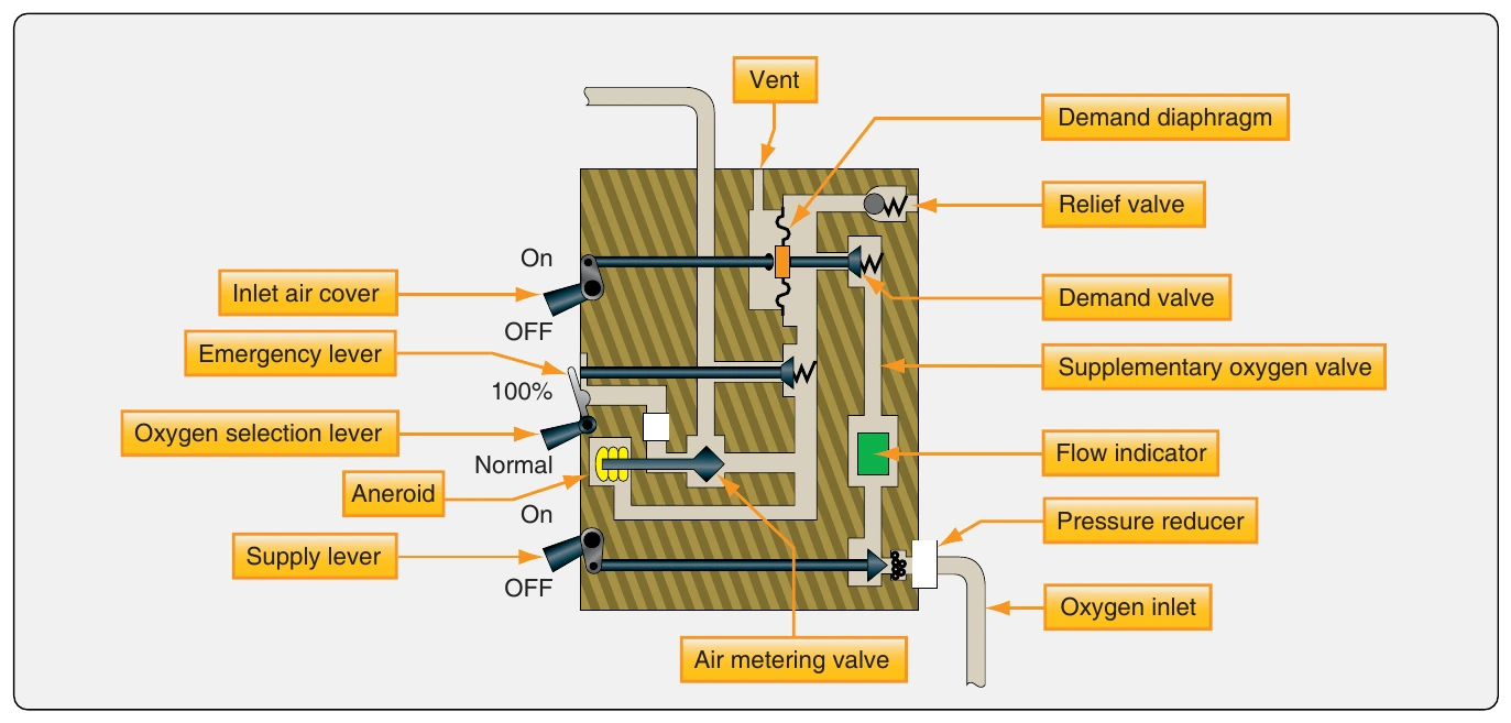
The diluter-demand type regulator holds back the flow of oxygen until the user inhales with a demand-type oxygen mask. The regulator dilutes the pure oxygen supply with cabin air each time a breath is drawn. With its control toggle switch set to normal, the amount of dilution depends on the cabin altitude. As altitude increases, an aneroid allows more oxygen and less cabin air to be delivered to the user by adjusting flows through a metering valve. At approximately 34,000 feet, the diluter-demand regulator meters 100 percent oxygen. This should not be needed unless cabin pressurization fails. Additionally, the user may select 100 percent oxygen delivery at any time by positioning the oxygen selection lever on the regulator. A built-in emergency switch also delivers 100 percent oxygen, but in a continuous flow as the demand function is bypassed. [Figure 16-21]
Pressure-demand oxygen systems operate similarly to diluter-demand systems, except that oxygen is delivered through the individual pressure regulator(s) under higher pressure. When the demand valve is unseated, oxygen under pressure forces its way into the lungs of the user. The demand function still operates, extending the overall supply of oxygen beyond that of a continuous-flow system. Dilution with cabin air also occurs if cabin altitude is less than 34,000 feet.
Pressure-demand regulators are used on aircraft that regularly fly at 40,000 feet and above. They are also found on many airliners and high-performance aircraft that may not typically fly that high. Forcing oxygen into the lungs under pressure ensures saturation of the blood, regardless of altitude or cabin altitude.
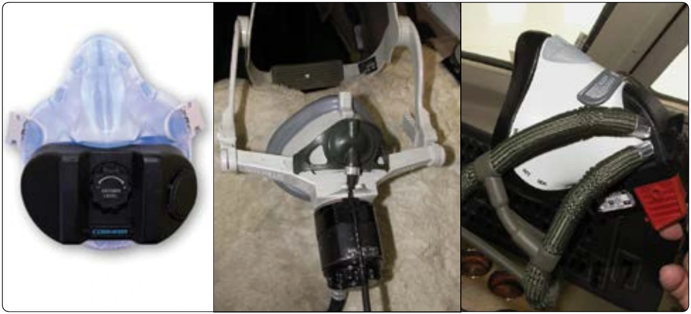
Both diluter-demand and pressure-demand regulators also come in mask-mounted versions. The operation is essentially the same as that of panel-mounted regulators. [Figure 16-22]
Flow Indicators
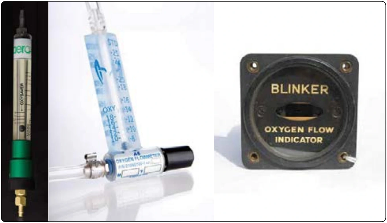
Flow indicators, or flow meters, are common in all oxygen systems. They usually consist of a lightweight object, or apparatus, that is moved by the oxygen stream. When flow exists, this movement signals the user in some way. [Figure 16-23] Many flow meters in continuous-flow oxygen systems also double as flow rate adjusters. Needle valves fitted into the flow indicator housing can fine-adjust the oxygen delivery rate. Demand-flow oxygen systems usually have flow indicators built into the individual regulators at each user station. Some contain a blinking device that activates when the user inhales and oxygen is delivered. Others move a colored pith object into a window. Regardless, flow indicators provide a quick verification that an oxygen system is functioning.
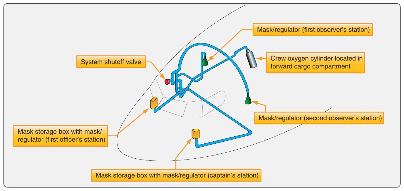
Different flow indicators are used to provide verification that the oxygen system is functioning. Other demand-flow indicators are built into the oxygen regulators. [Figure 16-23]
A recent development in general aviation oxygen systems is the electronic pulse demand oxygen delivery system (EDS). A small, portable EDS unit is made to connect between the oxygen source and the mask in a continuous-flow oxygen system. It delivers timed pulses of oxygen to the wearer on demand, saving oxygen normally lost during the hold and exhale segments of the breathing cycle. Advanced pressure sensing and processing allows the unit to deliver oxygen only when an inhalation starts. It can also sense differences in users’ breathing cycles and physiologies and adjust the flow of oxygen accordingly. A built-in pressure-sensing device adjusts the amount of oxygen released as altitude changes. [Figure 16-24]
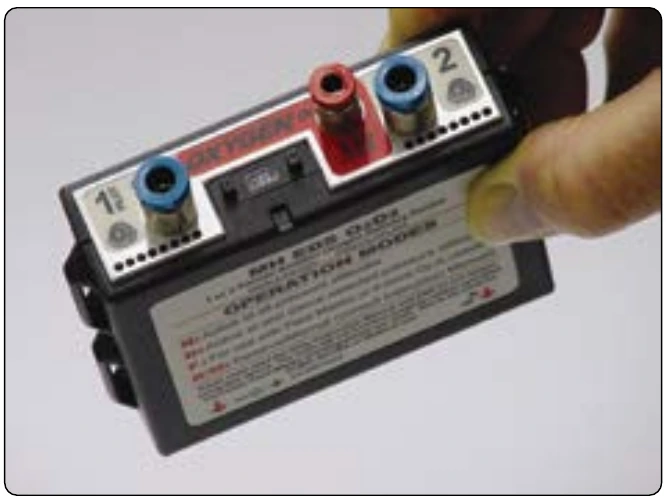
Permanently mounted EPD systems are also available. They typically integrate with an electronic valve/regulator on the oxygen cylinder and come with an emergency bypass switch to provide continuous-flow oxygen should the system malfunction. A liquid crystal display (LCD) monitor/control panel displays numerous system operating parameters and allows adjustments to the automatic settings. This type of electronic metering of oxygen has also been developed for passenger emergency oxygen use in airliners. [Figure 16-25]