
Chapter 2
Aerodynamics, Aircraft Assembly, & Rigging
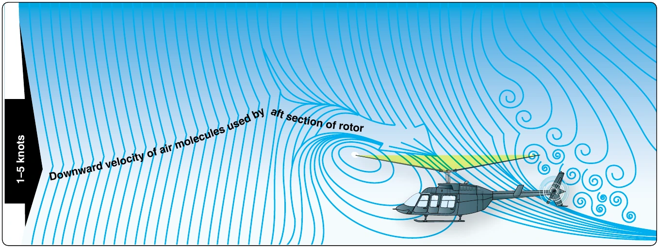
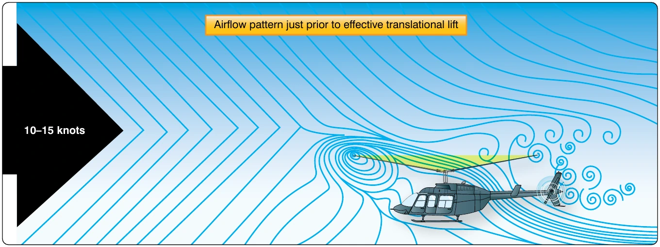
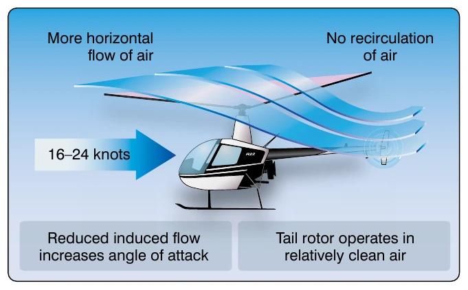
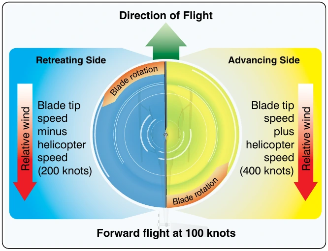
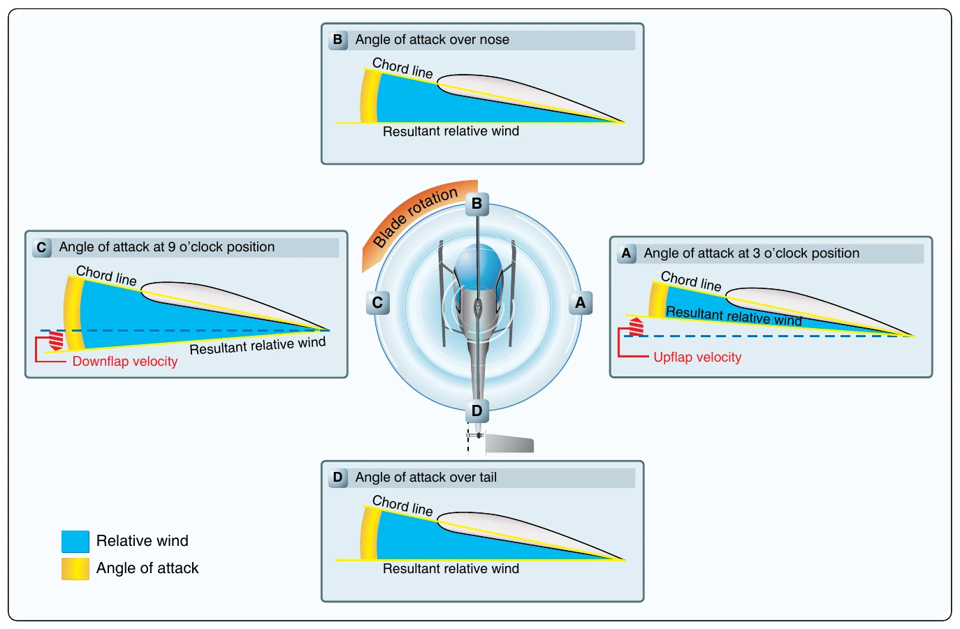
When the helicopter moves through the air, the relative airflow through the main rotor disc is different on the advancing side than on the retreating side. The relative wind encountered by the advancing blade is increased by the forward speed of the helicopter; while the relative windspeed acting on the retreating blade is reduced by the helicopter’s forward airspeed. Therefore, as a result of the relative windspeed, the advancing blade side of the rotor disc produces more lift than the retreating blade side. [Figure 2-40]
If this condition was allowed to exist, a helicopter with a counterclockwise main rotor blade rotation would roll to the left because of the difference in lift. In reality, the main rotor blades flap and feather automatically to equalize lift across the rotor disc. Articulated rotor systems, usually with three or more blades, incorporate a horizontal hinge (flapping hinge) to allow the individual rotor blades to move, or flap up and down as they rotate. A semirigid rotor system (two blades) utilizes a teetering hinge, which allows the blades to flap as a unit. When one blade flaps up, the other blade flaps down.
As the rotor blade reaches the advancing side of the rotor disc, it reaches its maximum upward flapping velocity. [Figure 2-41A] When the blade flaps upward, the angle between the chord line and the resultant relative wind decreases. This decreases the AOA, which reduces the amount of lift produced by the blade. At position C, the rotor blade is at its maximum downward flapping velocity. Due to downward flapping, the angle between the chord line and the resultant relative wind increases. This increases the AOA and thus the amount of lift produced by the blade.
The combination of blade flapping and slow relative wind acting on the retreating blade normally limits the maximum forward speed of a helicopter. At a high forward speed, the retreating blade stalls due to high AOA and slow relative wind speed. This situation is called “retreating blade stall” and is evidenced by a nose-up pitch, vibration, and a rolling tendency—usually to the left in helicopters with counterclockwise blade rotation. Pilots can avoid retreating blade stall by not exceeding the never-exceed speed. This speed is designated VNE and is indicated on a placard and marked on the airspeed indicator by a red line.
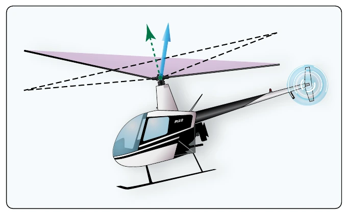
During aerodynamic flapping of the rotor blades as they compensate for dissymmetry of lift, the advancing blade achieves maximum upward flapping displacement over the nose and maximum downward flapping displacement over the tail. This causes the tip-path plane to tilt to the rear and is referred to as blowback. Figure 2-42 shows how the rotor disc is originally oriented with the front down following the initial cyclic input. As airspeed is gained and flapping eliminates dissymmetry of lift, the front of the disc comes up, and the back of the disc goes down. This reorientation of the rotor disc changes the direction in which total rotor thrust acts; the helicopter’s forward speed slows, but can be corrected with cyclic input. The pilot uses cyclic feathering to compensate for dissymmetry of lift allowing them to control the attitude of the rotor disc.
Cyclic feathering compensates for dissymmetry of lift (changes the AOA) in the following way. At a hover, equal lift is produced around the rotor system with equal pitch and AOA on all the blades and at all points in the rotor system (disregarding compensation for translating tendency). The rotor disc is parallel to the horizon. To develop a thrust force, the rotor system must be tilted in the desired direction of movement. Cyclic feathering changes the angle of incidence differentially around the rotor system. Forward cyclic movements decrease the angle of incidence at one part on the rotor system while increasing the angle at another part. Maximum downward flapping of the blade over the nose and maximum upward flapping over the tail tilt both rotor disc and thrust vector forward. To prevent blowback from occurring, the pilot must continually move the cyclic forward as the velocity of the helicopter increases. Figure 2-42 illustrates the changes in pitch angle as the cyclic is moved forward at increased airspeeds. At a hover, the cyclic is centered and the pitch angle on the advancing and retreating blades is the same. At low forward speeds, moving the cyclic forward reduces pitch angle on the advancing blade and increases pitch angle on the retreating blade. This causes a slight rotor tilt. At higher forward speeds, the pilot must continue to move the cyclic forward. This further reduces pitch angle on the advancing blade and further increases pitch angle on the retreating blade. As a result, there is even more tilt to the rotor than at lower speeds.
This horizontal lift component (thrust) generates higher helicopter airspeed. The higher airspeed induces blade flapping to maintain symmetry of lift. The combination of flapping and cyclic feathering maintains symmetry of lift and desired attitude on the rotor system and helicopter.
Autorotation
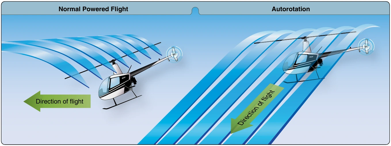
Autorotation is the state of flight in which the main rotor system of a helicopter is being turned by the action of air moving up through the rotor rather than engine power driving the rotor. [Figure 2-43] In normal, powered flight, air is drawn into the main rotor system from above and exhausted downward, but during autorotation, air moves up into the rotor system from below as the helicopter descends. Autorotation is permitted mechanically by a freewheeling unit, which is a special clutch mechanism that allows the main rotor to continue turning even if the engine is not running. If the engine fails, the freewheeling unit automatically disengages the engine from the main rotor allowing the main rotor to rotate freely. It is the means by which a helicopter can be landed safely in the event of an engine failure; consequently, all helicopters must demonstrate this capability in order to be certificated.
Rotorcraft Controls
Swash Plate Assembly
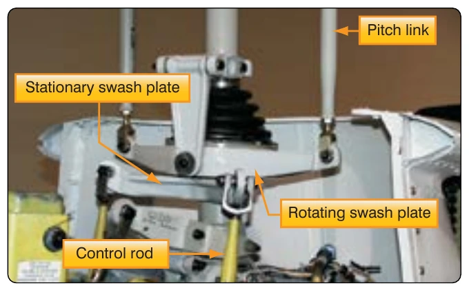
The purpose of the swash plate is to transmit control inputs from the collective and cyclic controls to the main rotor blades. It consists of two main parts: the stationary swash plate and the rotating swash plate. [Figure 2-44] The stationary swash plate is mounted around the main rotor mast and connected to the cyclic and collective controls by a series of pushrods. It is restrained from rotating by an antidrive link but is able to tilt in all directions and move vertically. The rotating swash plate is mounted to the stationary swash plate by a uniball sleeve. It is connected to the mast by drive links and is allowed to rotate with the main rotor mast. Both swash plates tilt and slide up and down as one unit. The rotating swash plate is connected to the pitch horns by the pitch links.