
Chapter 2
Aerodynamics, Aircraft Assembly, & Rigging
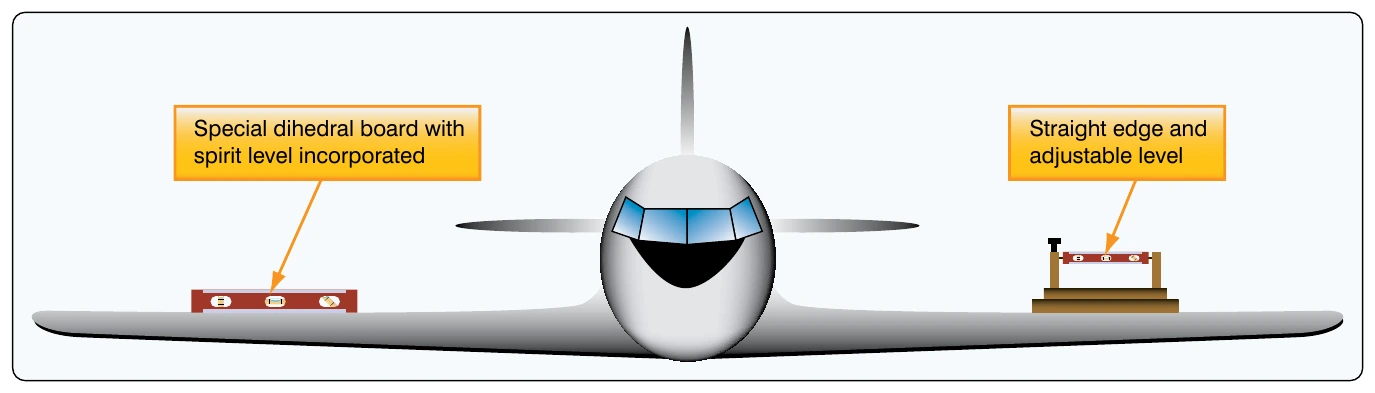
The dihedral angle should be checked in the specified positions using the special boards provided by the aircraft manufacturer. If no such boards are available, a straight edge and a inclinometer can be used. Dihedral is normally checked using the front spar. The methods for checking dihedral are shown in Figure 2-84.
It is important that the dihedral be checked at the positions specified by the manufacturer. Certain portions of the wings or horizontal stabilizer may sometimes be horizontal or, on rare occasions, anhedral angles may be present.
Checking Incidence
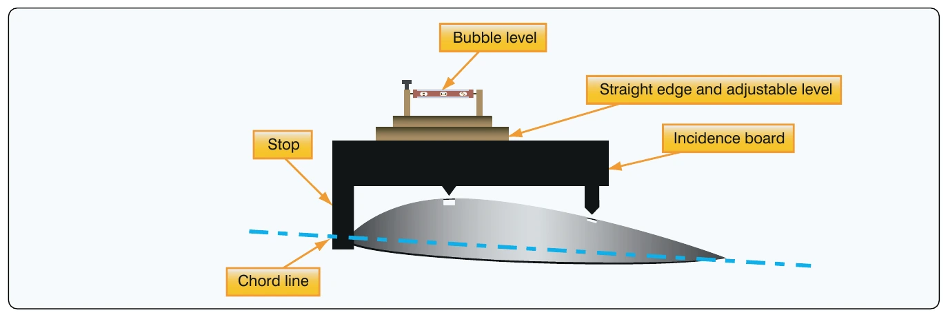
Incidence is usually checked in at least two specified positions on the surface of the wing to ensure that the wing is free from twist. A variety of incidence boards are used to check the incidence angle. Some have stops at the forward edge, which must be placed in contact with the leading edge of the wing. Others are equipped with location pegs which fit into some specified part of the structure. The purpose in either case is to ensure that the board is fitted in exactly the position intended. In most instances, the boards are kept clear of the wing contour by short extensions attached to the board. A typical incidence board is shown in Figure 2-85.
When used, the board is placed at the specified locations on the surface being checked. If the incidence angle is correct, a inclinometer on top of the board reads zero, or within a specified tolerance of zero. Modifications to the areas where incidence boards are located can affect the reading. For example, if leading edge deicer boots have been installed, the position of a board having a leading edge stop is affected.
Checking Fin Verticality
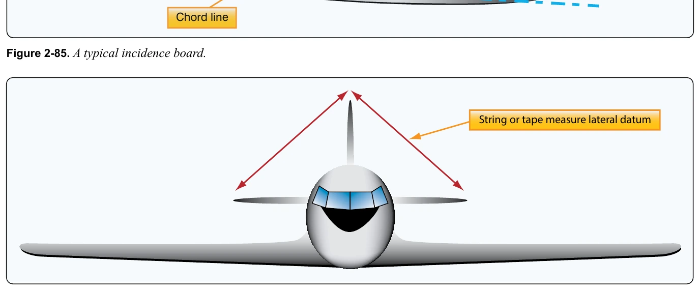
After the rigging of the horizontal stabilizer has been checked, the verticality of the vertical stabilizer relative to the lateral datum can be checked. The measurements are taken from a given point on either side of the top of the fin to a given point on the left and right horizontal stabilizers. [Figure 2-86] The measurements should be similar within prescribed limits. When it is necessary to check the alignment of the rudder hinges, remove the rudder and pass a plumb bob line through the rudder hinge attachment holes. The line should pass centrally through all the holes. It should be noted that some aircraft have the leading edge of the vertical fin offset to the longitudinal center line to counteract engine torque.
Checking Engine Alignment
manual. [Figure 2-87]
Symmetry Check
maintenance manual.
taken using a steel tape. When measuring long distances, it is suggested that a spring scale be used with the tape to obtain equal tension. A five-pound pull is usually sufficient.
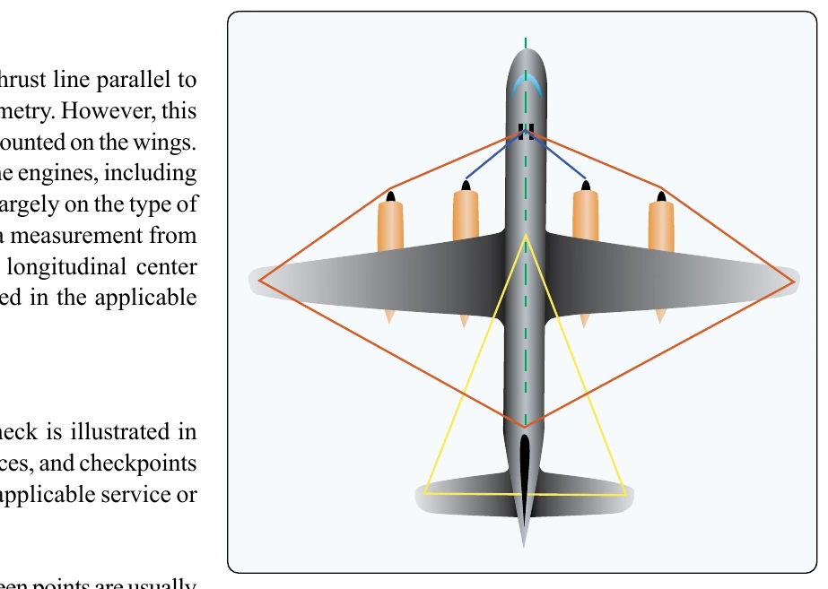
On large aircraft, the positions at which the dimensions are to be taken are usually chalked on the floor. This is done by suspending a plumb bob from the checkpoints and marking the floor immediately under the point of each plumb bob. The measurements are then taken between the centers of each marking.
Cable Tension
When it has been determined that the aircraft is symmetrical and structural alignment is within specifications, the cable tension and control surface travel can be checked. To determine the amount of tension on a cable, a tensiometer is used. When properly maintained, a tensiometer is 98 percent accurate. Tensiometers are calibrated to maintain accuracy. Cable tension is determined by measuring the amount of force needed to make an offset in the cable between two hardened steel blocks called anvils. A riser or plunger is pressed against the cable to form the offset. Several manufacturers make a variety of tensiometers, each type designed for different kinds of cable, cable sizes, and cable tensions. One type of tensiometer is illustrated in Figure 2-88.