Chapter 4
Aircraft Metal Structural Repair
There are four types of drill bushing holder:
- Standard—fine for drilling flat stock or tubing/rod; uses insert-type bushings.
- Egg cup—improvement on standard tripod base; allows drilling on both flat and curved material; interchangeable bushings allows flexibility. [Figure 4-51]
- Plate—used primarily for interchangeable production components; uses commercial bushings and self-feeding drills.
- Arm—used when drilling critical structure; can be locked in position; uses interchangeable commercial bushings.
Hole Drilling Techniques
Precise location of drilled holes is sometimes required. When locating holes to close tolerances, accurately located punch marks need to be made. If a punch mark is too small, the chisel edge of the drill bit may bridge it and “walk off” the exact location before starting. If the punch mark is too heavy, it may deform the metal and/or result in a local strain hardening where the drill bit is to start cutting. The best size for a punch mark is about the width of the chisel edge of the drill bit to be used. This holds the drill point in place while starting. The procedure that ensures accurate holes follows: [Figure 4-52]
- Measure and lay out the drill locations carefully and mark with crossed lines. Note: The chisel edge is the least efficient operating
surface element of the twist drill bit because it does not cut, but actually squeezes or extrudes the work material.
- Use a sharp prick punch or spring-loaded center punch and magnifying glass to further mark the holes.
- Seat a properly ground center punch (120°–135°) in the prick punch mark and, holding the center punch perpendicular to the surface, strike a firm square blow with a hammer.
- Mark each hole with a small drill bit (1⁄16-inch recommended) to check and adjust the location prior to pilot drilling.
- For holes 3⁄16-inch and larger, pilot drilling is recommended. Select a drill bit equal to the width of the chisel edge of the final drill bit size. Avoid using a pilot drill bit that is too large because it would cause the corners and cutting lips of the final drill bit to be dulled, burned, or chipped. It also contributes to chattering and drill motor stalling. Pilot drill at each mark.
- Place the drill point at the center of the crossed lines, perpendicular to the surface, and, with light pressure, start drilling slowly. Stop drilling after a few turns and check to see if the drill bit is starting on the mark. It should be; if not, it is necessary to walk the hole a little by pointing the drill in the direction it should go, and rotating it carefully and intermittently until properly lined up.
- Enlarge each pilot drilled hole to final size.
Drilling Large Holes
The following technique can be used to drill larger holes. Special tooling has been developed to drill large holes to precise tolerances. [Figure 4-53]
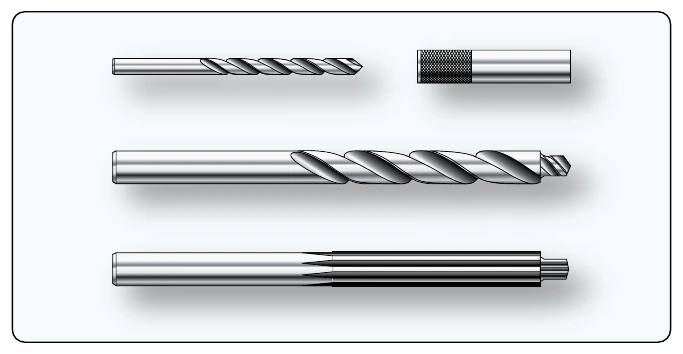
- Pilot drill using a drill bushing. Bushings are sized for 1⁄8, 3⁄16, or 1⁄4 drill bits.
- Step drill bits are used to step the hole to approximately 1⁄64-inch smaller than the final hole size. The aligning step diameter matches the pilot drill bit size.
- Finish ream to size using a step reamer. The aligning step diameter matches the core drill bit size. Reamers should be available for both clearance and interference fit hole sizes. Note: Holes can also be enlarged by using a series of step reamers.
Chip Chasers
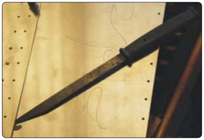
The chip chaser is designed to remove chips and burrs lodged between sheets of metal after drilling holes for riveting. [Figure 4-54] Chip chasers have a plastic molded handle and a flexible steel blade with a hook in the end.
Forming Tools
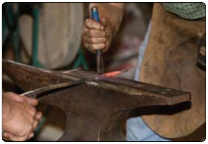
Sheet metal forming dates back to the days of the blacksmith who used a hammer and hot oven to mold metal into the desired form. Today’s aircraft technician relies on a wide variety of powered and hand-operated tools to precisely bend and fold sheet metal to achieve the perfect shape. Forming tools include straight line machines, such as the bar folder and press brake, as well as rotary machines, such as the slip roll former. Forming sheet metal requires a variety of tools and equipment (both powered and manual), such as the piccolo former, shrinking and stretching tools, form blocks, and specialized hammers and mallets. [Figure 4-55]
Tempered sheet stock is used in forming operations whenever possible in typical repairs. Forming that is performed in the tempered condition, usually at room temperature, is known as cold-forming. Cold forming eliminates heat treatment and the straightening and checking operations required to remove the warp and twist caused by the heat treating process. Cold-formed sheet metal experiences a phenomenon known as spring-back, which causes the worked piece to spring back slightly when the deforming force is removed. If the material shows signs of cracking during cold forming over small radii, the material should be formed in the annealed condition.