
Chapter 4
Aircraft Metal Structural Repair
Power press brakes can be set up with back stops (some are computer controlled) for high volume production. Press brake operations are usually done manually and require skill and knowledge of safe use.
Slip Roll Former
With the exception of the brake, the slip roll is probably used more than any other machine in the shop. [Figure 4-60] This machine is used to form sheets into cylinders or other straight curved surfaces. It consists of right and left end frames with three solid rolls mounted in between. Gears, which are operated by either a hand crank or a power drive, connect the two gripping rolls. These rolls can be adjusted to the thickness of the metal by using the two adjusting screws located on the bottom of each frame. The two most common of these forming machines are the slip roll former and the rotary former. Available in various sizes and capabilities, these machines come in manual or powered versions.
The slip roll former in Figure 4-60 is manually operated and consists of three rolls, two housings, a base, and a handle. The handle turns the two front rolls through a system of gears enclosed in the housing. The front rolls serve as feeding, or gripping, rolls. The rear roll gives the proper curvature to the work. When the metal is started into the machine, the rolls grip the metal and carry it to the rear roll, which curves it. The desired radius of a bend is obtained by the rear roll. The bend radius of the part can be checked as the forming operation progresses by using a circle board or radius gauge. The gauges can be made by cutting a piece of material to the required finished radius and comparing it to the radius being formed by the rolling operation. On some material, the forming operation must be performed by passing the material through the rolls several times with progressive settings on the forming roll. On most machines, the top roll can be released on one end, permitting the formed sheet to be removed from the machine without distortion.
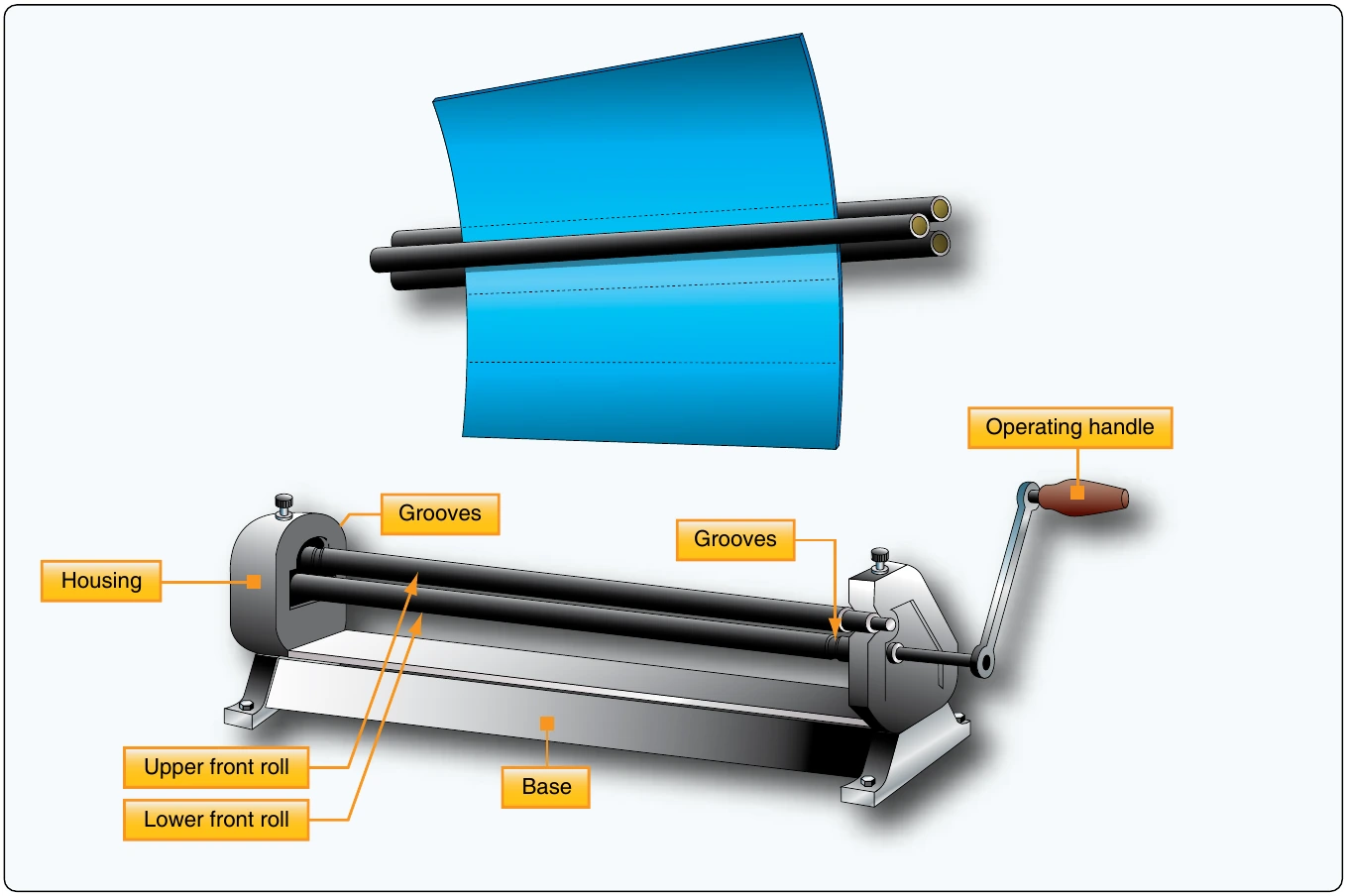
The front and rear rolls are grooved to permit forming of objects that have wired edges. The upper roll is equipped with a release that permits easy removal of the metal after it has been formed. When using the slip roll former, the lower front roll must be raised or lowered before inserting the sheet of metal. If the object has a folded edge, there must be enough clearance between the rolls to prevent flattening the fold. If a metal requiring special care (such as aluminum) is being formed, the rolls must be clean and free of imperfections.
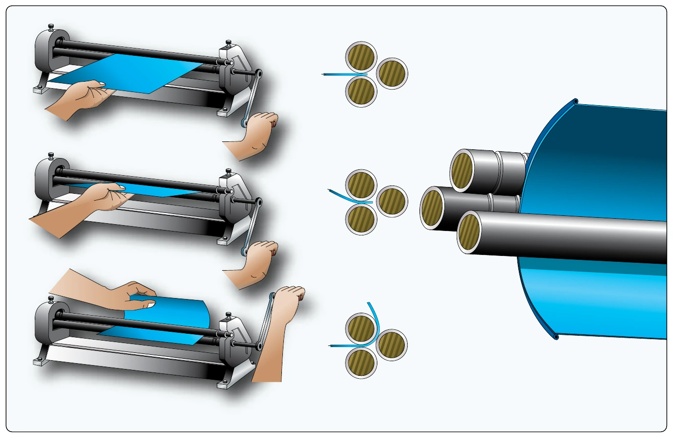
The rear roll must be adjusted to give the proper curvature to the part being formed. There are no gauges that indicate settings for a specific diameter; therefore, trial and error settings must be used to obtain the desired curvature. The metal should be inserted between the rolls from the front of the machine. Start the metal between the rolls by rotating the operating handle in a clockwise direction. A starting edge is formed by holding the operating handle firmly with the right hand and raising the metal with the left hand. The bend of the starting edge is determined by the diameter of the part being formed. If the edge of the part is to be flat or nearly flat, a starting edge should not be formed.
Ensure that fingers and loose clothing are clear of the rolls before the actual forming operation is started. Rotate the operating handle until the metal is partially through the rolls and change the left hand from the front edge of the sheet to the upper edge of the sheet. Then, roll the remainder of the sheet through the machine. If the desired curvature is not obtained, return the metal to its starting position by rotating the handle counterclockwise. Raise or lower the rear roll and roll the metal through the rolls again. Repeat this procedure until the desired curvature is obtained, then release the upper roll and remove the metal. If the part to be formed has a tapered shape, the rear roll should be set so that the rolls are closer together on one end than on the opposite end. The amount of adjustment must be determined by experimentation. If the job being formed has a wired edge, the distance between the upper and lower rolls and the distance between the lower front roll and the rear roll should be slightly greater at the wired end than at the opposite end. [Figure 4-61]
Rotary Machine
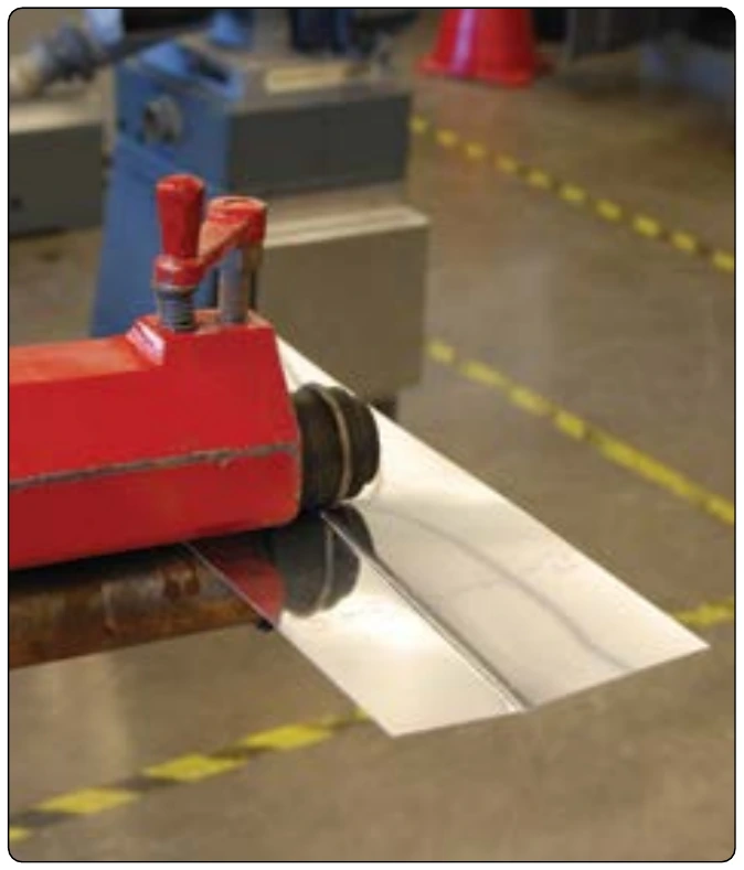
The rotary machine is used on cylindrical and flat sheet metal to shape the edge or to form a bead along the edge. [Figure 4-62] Various shaped rolls can be installed on the rotary machine to perform these operations. The rotary machine works best with thinner annealed materials.
Stretch Forming
In the process of stretch forming, a sheet of metal is shaped by stretching it over a formed block to just beyond the elastic limit where permanent set takes place with a minimum amount of spring-back. To stretch the metal, the sheet is rigidly clamped at two opposite edges in fixed vises. Then, the metal is stretched by moving a ram that carries the form block against the sheet with the pressure from the ram causing the material to stretch and wrap to the contour of the form block.
Stretch forming is normally restricted to relatively large parts with large radii of curvature and shallow depth, such as contoured skin. Uniform contoured parts produced at a faster speed give stretch forming an advantage over hand formed parts. Also, the condition of the material is more uniform than that obtained by hand forming.
Drop Hammer
The drop hammer forming process produces shapes by the progressive deformation of sheet metal in matched dies under the repetitive blows of a gravity-drop hammer or a power-drop hammer. The configurations most commonly formed by the process include shallow, smoothly contoured double-curvature parts, shallow-beaded parts, and parts with irregular and comparatively deep recesses. Small quantities of cup-shaped and box-shaped parts, curved sections, and contoured flanged parts are also formed. Drop hammer forming is not a precision forming method and cannot provide tolerances as close as 0.03-inch to 0.06-inch. Nevertheless, the process is often used for sheet metal parts, such as aircraft components, that undergo frequent design changes, or for which there is a short run expectancy.
Hydropress Forming
The rubber pad hydropress can be utilized to form many varieties of parts from aluminum and its alloys with relative ease. Phenolic, masonite, kirksite, and some types of hard setting moulding plastic have been used successfully as form blocks to press sheet metal parts, such as ribs, spars, fans, etc. To perform a press forming operation:
- Cut a sheet metal blank to size and deburr edges.
- Set the form block (normally male) on the lower press platen.
- Place the prepared sheet metal blank (with locating pins to prevent shifting of the blank when the pressure is applied).
- Lower or close the rubber pad-filled press head over the form block and the rubber envelope.
- The form block forces the blank to conform to its contour.