
Chapter 4
Aircraft Metal Structural Repair
National Advisory Committee for Aeronautics (NACA) Method of Double Flush Riveting
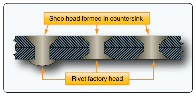
A rivet installation technique known as the National Advisory Committee for Aeronautics (NACA) method has primary applications in fuel tank areas. [Figure 4-99] To make a NACA rivet installation, the shank is upset into a 82° countersink. In driving, the gun may be used on either the head or shank side. The upsetting is started with light blows, then the force increased and the gun or bar moved on the shank end so as to form a head inside the countersink well. If desired, the upset head may be shaved flush after driving. If utilizing this method, it is important to reference the manufacturer’s instructions for repair or replacement.
Special Purpose Fasteners
Special purpose fasteners are designed for applications in which fastener strength, ease of installation, or temperature properties of the fastener require consideration. Solid shank rivets have been the preferred construction method for metal aircraft for many years because they fill up the hole, which results in good load transfer, but they are not always ideal. For example, the attachment of many nonstructural parts (aircraft interior furnishings, flooring, deicing boots, etc.) do not need the full strength of solid shank rivets.
To install solid shank rivets, the aircraft technician must have access to both sides of a riveted structure or structural part. There are many places on an aircraft where this access is impossible or where limited space does not permit the use of a bucking bar. In these instances, it is not possible to use solid shank rivets, and special fasteners have been designed that can be bucked from the front. [Figure 4-100] There are also areas of high loads, high fatigue, and bending on aircraft. Although the shear loads of riveted joints are very good, the tension, or clamp-up, loads are less than ideal.
Special purpose fasteners are sometimes lighter than solid shank rivets, yet strong enough for their intended use. These fasteners are manufactured by several corporations and have unique characteristics that require special installation tools, special installation procedures, and special removal procedures. Because these fasteners are often inserted in locations where one head, usually the shop head, cannot be seen, they are called blind rivets or blind fasteners.
Typically, the locking characteristics of a blind rivet are not as good as a driven rivet. Therefore, blind rivets are usually not used when driven rivets can be installed. Blind rivets shall not be used:
- In fluid-tight areas.
- On aircraft in air intake areas where rivet parts may be ingested by the engine.
- On aircraft control surfaces, hinges, hinge brackets, flight control actuating systems, wing attachment fittings, landing gear fittings, on floats or amphibian
hulls below the water level, or other heavily stressed locations on the aircraft.
Blind Rivets
The first blind fasteners were introduced in 1940 by the Cherry Rivet Company (now Cherry® Aerospace), and the aviation industry quickly adopted them. The past decades have seen a proliferation of blind fastening systems based on the original concept, which consists of a tubular rivet with a fixed head and a hollow sleeve. Inserted within the rivet’s core is a stem that is enlarged or serrated on its exposed end when activated by a pulling-type rivet gun. The lower end of the stem extends beyond the inner sheet of metal. This portion contains a tapered joining portion and a blind head that has a larger diameter than the stem or the sleeve of the tubular rivet.
When the pulling force of the rivet gun forces the blind head upward into the sleeve, its stem upsets or expands the lower end of the sleeve into a tail. This presses the inner sheet upward and closes any space that might have existed between it and the outer sheet. Since the exposed head of the rivet is held tightly against the outer sheet by the rivet gun, the sheets of metal are clamped, or clinched, together.
Friction-Locked Blind Rivets
Standard self-plugging blind rivets consist of a hollow sleeve and a stem with increased diameter in the plug section. The blind head is formed as the stem is pulled into the sleeve. Friction-locked blind rivets have a multiple-piece construction and rely on friction to lock the stem to the sleeve. As the stem is drawn up into the rivet shank, the stem portion upsets the shank on the blind side, forming a plug in the hollow center of the rivet. The excess portion of the stem breaks off at a groove due to the continued pulling action of the rivet gun. Metals used for these rivets are 2117- T4 and 5056-F aluminum alloy. Monel® is used for special applications.
Many friction-locked blind rivet center stems fall out due to vibration, which greatly reduces its shear strength. To combat that problem, most friction-lock blind rivets are replaced by the mechanical-lock, or stem-lock, type of blind fasteners. However, some types, such as the Cherry SPR® 3⁄32-inch Self-Plugging Rivet, are ideal for securing nutplates located in inaccessible and hard-to-reach areas where bucking or squeezing of solid rivets is unacceptable. [Figure 4-101]