
Chapter 4
Aircraft Metal Structural Repair
Folding sheet metal is to make a bend or crease in sheets, plates, or leaves. Folds are usually thought of as sharp, angular bends and are generally made on folding machines such as the box and pan brake discussed earlier in this chapter.
Layout & Forming
Terminology
The following terms are commonly used in sheet metal forming and flat pattern layout. Familiarity with these terms aids in understanding how bend calculations are used in a bending operation. Figure 4-120 illustrates most of these terms.
Base measurement—the outside dimensions of a formed part. Base measurement is given on the drawing or blueprint or may be obtained from the original part.
Leg—the longer part of a formed angle.
Flange—the shorter part of a formed angle—the opposite of leg. If each side of the angle is the same length, then each is known as a leg.
Grain of the metal—natural grain of the material is formed as the sheet is rolled from molten ingot. Bend lines should be made to lie at a 90º angle to the grain of the metal if possible.
Bend allowance (BA)—refers to the curved section of metal within the bend (the portion of metal that is curved in bending). The bend allowance may be considered as being the length of the curved portion of the neutral line.
Bend radius—the arc is formed when sheet metal is bent. This arc is called the bend radius. The bend radius is measured from a radius center to the inside surface of the metal. The minimum bend radius depends on the temper, thickness, and type of material. Always use a Minimum Bend Radius Table to determine the minimum bend radius for the alloy that is going to be used. Minimum bend radius charts can be found in manufacturer’s maintenance manuals.
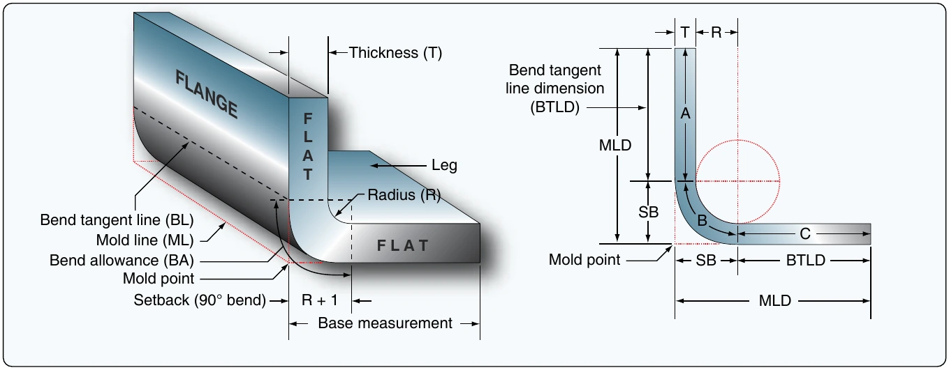
Bend tangent line (BL)—the location at which the metal starts to bend and the line at which the metal stops curving. All the space between the bend tangent lines is the bend allowance.
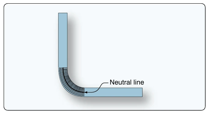
Neutral axis—an imaginary line that has the same length after bending as it had before bending. [Figure 4-121] After bending, the bend area is 10 to 15 percent thinner than before bending. This thinning of the bend area moves the neutral line of the metal in towards the radius center. For calculation purposes, it is often assumed that the neutral axis is located at the center of the material, although the neutral axis is not exactly in the center of the material. However, the amount of error incurred is so slight that, for most work, assuming it is at the center is satisfactory.
Mold line (ML)—an extension of the flat side of a part beyond the radius.
Mold line dimension (MLD)—the dimension of a part made by the intersection of mold lines. It is the dimension the part would have if its corners had no radius.
Mold point—the point of intersection of the mold lines. The mold point would be the outside corner of the part if there were no radius.
K-Factor—the percentage of the material thickness where there is no stretching or compressing of the material, such as the neutral axis. This percentage has been calculated and is one of 179 numbers on the K chart corresponding to one of the angles between 0° and 180° to which metal can be bent. [Figure 4-122] Whenever metal is to be bent to any angle other than 90° (K-factor of 90° equal to 1), the corresponding K-factor number is selected from the chart and is multiplied by the sum of the radius (R) and the thickness (T) of the metal. The product is the amount of setback (see next paragraph) for the bend. If no K chart is available, the K-factor can be calculated with a calculator by using the following formula: the K value is the tangent of one-half the bend angle.
The setback dimension must be determined prior to making the bend because setback is used in determining the location of the beginning bend tangent line. When a part has more than one bend, setback must be subtracted for each bend. The majority of bends in sheet metal are 90° bends. The K-factor must be used for all bends that are smaller or larger than 90°.