
Chapter 4
Aircraft Metal Structural Repair
will be discussed. [Figure 4-123] When using bend allowance calculations, the following steps for finding the total developed length can be computed with formulas, charts, or computer-aided design (CAD) and computer-aided manufacturing (CAM) software packages. This channel is made of 0.040-inch 2024-T3 aluminum alloy.
Step 1: Determine the Correct Bend Radius
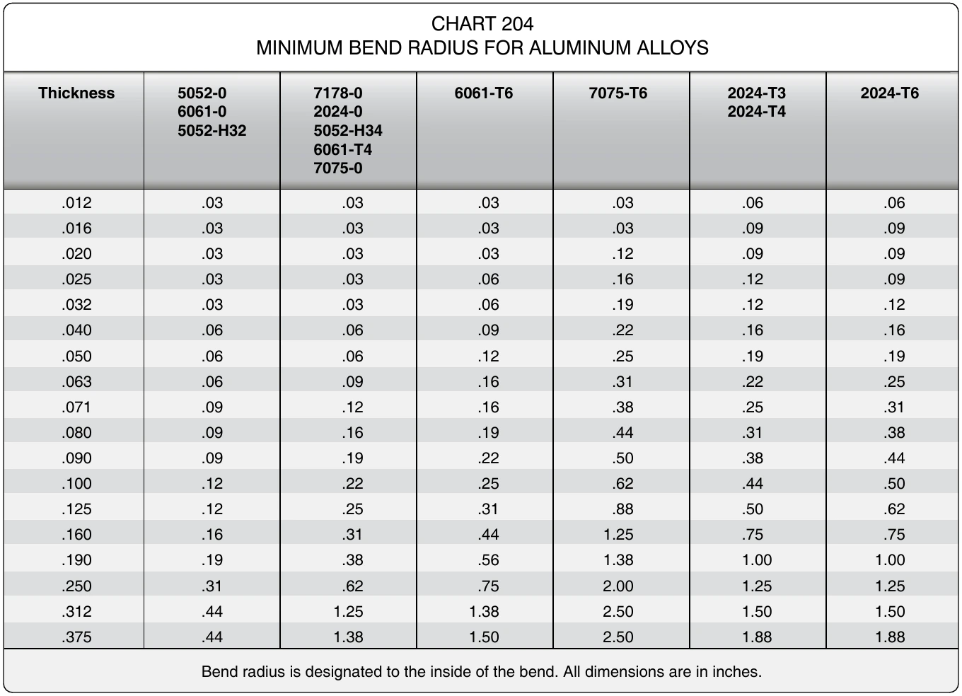
Minimum bend radius charts are found in manufacturers’ maintenance manuals. A radius that is too sharp cracks the material during the bending process. Typically, the drawing indicates the radius to use, but it is a good practice to double check. For this layout example, use the minimum radius chart in Figure 4-124 to choose the correct bend radius for the alloy, temper, and the metal thickness. For 0.040, 2024- T3 the minimum allowable radius is 0.16-inch or 5⁄32-inch.
Step 2: Find the Setback
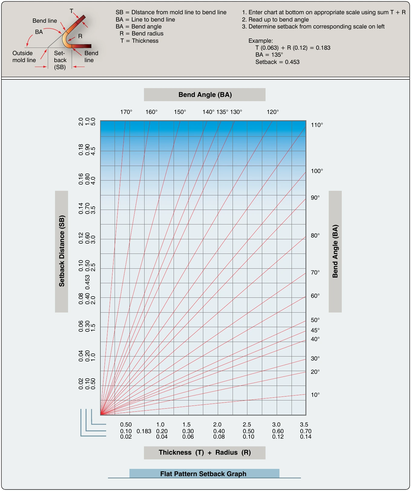
The setback can be calculated with a formula or can be found in a setback chart available in aircraft maintenance manuals or Source, Maintenance, and Recoverability books (SMRs). [Figure 4-125]
Using a Formula to Calculate the Setback
Since all of the angles in this example are 90° angles, the setback is calculated as follows:
Using a Setback Chart to Find the Setback The setback chart is a quick way to find the setback and is useful for open and closed bends, because there is no need to calculate or find the K-factor. Several software packages and online calculators are available to calculate the setback. These programs are often used with CAD/CAM programs. [Figure 4-125]
- Enter chart at the bottom on the appropriate scale with the sum of the radius and material thickness.
- Read up to the bend angle.
- Find the setback from corresponding scale on the left.
Find 0.183 at the bottom of the graph. It is found in the middle scale.
- Read up to a bend angle of 135°.
- Locate the setback at the left hand side of the graph in the middle scale (0.435-inch). [Figure 4-125]
Step 3: Find the Length of the Flat Line Dimension
The flat line dimension can be found using the formula: