
Chapter 9
Aircraft Electrical System
The square root of both sides of the equation gives:
This formula can be used to determine the impedance when the values of inductive reactance and resistance are known. It can be modified to solve for impedance in circuits containing capacitive reactance and resistance by substituting XC in the formula in place of XL. In circuits containing resistance with both inductive and capacitive reactance, the reactances can be combined; but because their effects in the circuit are exactly opposite, they are combined by subtraction (the smaller number is always subtracted from the larger):
or
Figure 9-25 shows example 1. Here, a series circuit containing a resistor and an inductor are connected to a source of 110 volts at 60 cycles per second. The resistive element is a simple measuring 6 ohms, and the inductive element is a coil with an inductance of 0.021 henry. What is the value of the impedance and the current through the circuit?
Solution: First, the inductive reactance of the coil is computed:
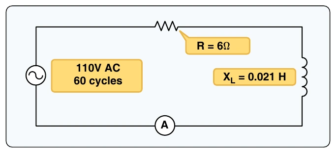
Next, the total impedance is computed:
Remember when making calculations for Z always use inductive reactance not inductance, and use capacitive reactance, not capacitance.
Once impedance is found, the total current can be calculated.
Since this circuit is resistive and inductive, there is a phase shift where voltage leads current.
Example 2 is a series circuit illustrated in which a capacitor of 200 μf is connected in series with a 10 ohm resistor. [Figure 9-26] What is the value of the impedance, the current flow, and the voltage drop across the resistor?
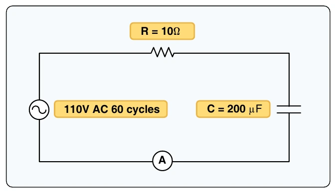
Solution: First, the capacitance is changed from microfarads to farads.