Chapter 9
Aircraft Electrical System
Next solve for capacitive reactance:
To find the impedance,
Since this circuit is resistive and capacitive, there is a phase shift where current leads voltage:
To find the current:
To find the voltage drop across the resistor (ER):
To find the voltage drop over the capacitor (EC):
The sum of these two voltages does not equal the applied voltage, since the current leads the voltage. Use the following formula to find the applied voltage:
When the circuit contains resistance, inductance, and capacitance, the following equation is used to find the impedance.
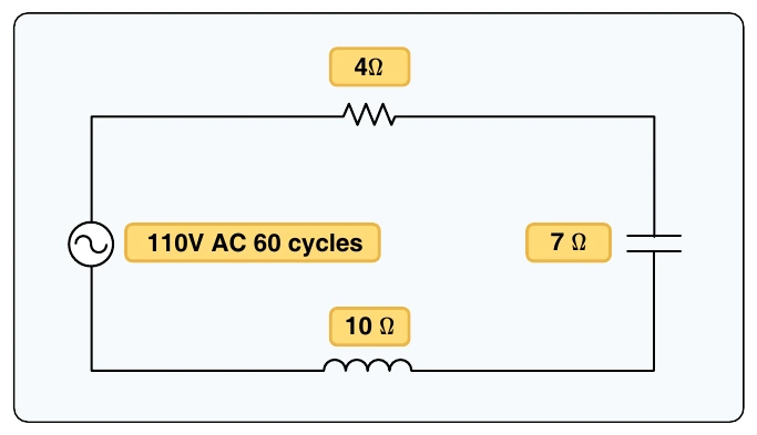
Example 3: What is the impedance of a series circuit consisting of a capacitor with a capacitive reactance of 7 ohms, an inductor with an inductive reactance of 10 ohms, and a resistor with a resistance of 4 ohms? [Figure 9-27]
Solution: