
Chapter 9
Aircraft Electrical System
To determine the current flow in the circuit:
To determine the current flow through each parallel path of the circuit, calculate IR, IL, and IC.
It should be noted that the total current flow of parallel circuits is found by using vector addition of the individual current flows as follows:
Power in AC Circuits
Since voltage and current determine power, there are similarities in the power consumed by both AC and DC circuits. In AC however, current is a function of both the resistance and the reactance of the circuit. The power consumed by any AC circuit is a function of the applied voltage and both circuit’s resistance and reactance. AC circuits have two distinct types of power, one created by the resistance of the circuit and one created by the reactance of the circuit.
True Power
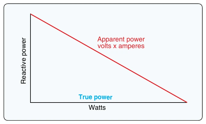
True power of any AC circuit is commonly referred to as the working power of the circuit. True power is the power consumed by the resistance portion of the circuit and is measured in watts (W). True power is symbolized by the letter P and is indicated by any wattmeter in the circuit. True power is calculated by the formula:
Apparent Power
Apparent power in an AC circuit is sometimes referred to as the reactive power of a circuit. Apparent power is the power consumed by the entire circuit, including both the resistance and the reactance. Apparent power is symbolized by the letter S and is measured in volt-amps (VA). Apparent power is a product of the effective voltage multiplied by the effective current. Apparent power is calculated by the formula:
Power Factor
As seen in Figure 9-30, the resistive power and the reactive power effect the circuit at right angles to each other. The power factor in an AC circuit is created by this right angle effect.
Power factor can be defined as the mathematical difference between true power and apparent power. Power factor (PF) is a ratio and always a measurement between 0 and 100. The power factor is directly related to the phase shift of a circuit. The greater the phase shift of a circuit the lower the power factor. For example, an AC circuit that is purely inductive (contains reactance only and no resistance) has a phase shift of 90° and a power factor of 0.0. An AC circuit that is purely resistive (has no reactance) has a phase shift of 0 and a power factor of 100. Power factor is calculated by using the following formula: