
Chapter 5
Physics for Aviation
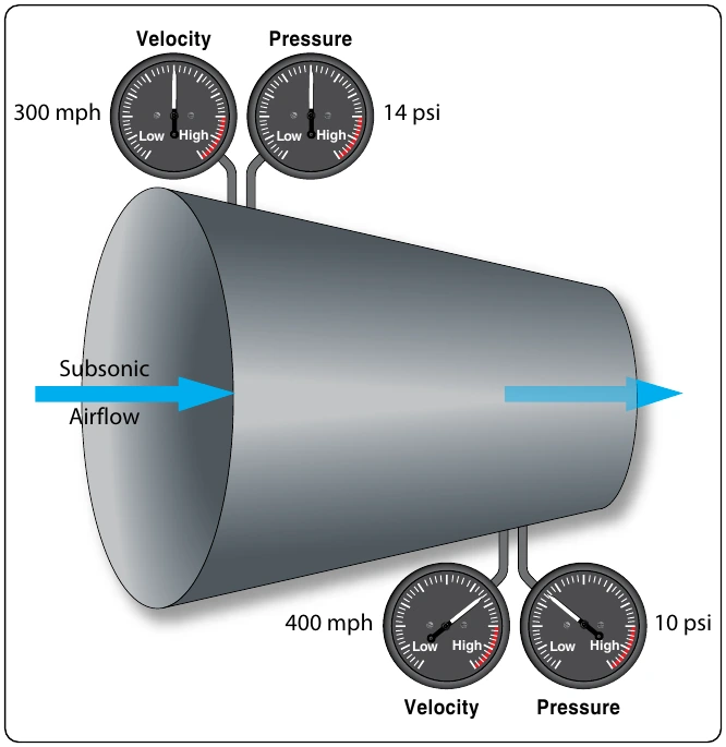
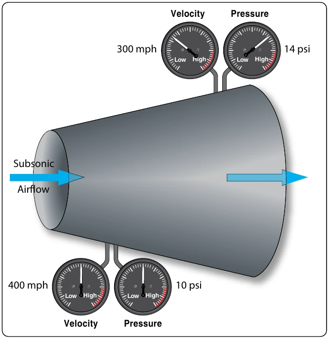
In a diverging duct, just the opposite would happen. From the entry point to the exit point, the duct is spreading out and the area is getting larger. [Figure 5-55] With the increase in cross-sectional area, the velocity of the air decreases and the static pressure increases. The total energy in the air has not changed. What has been lost in velocity, which is kinetic energy, is gained in static pressure, which is potential energy.
In the discussion of Bernoulli’s principle earlier in this chapter, a venturi was shown in Figure 5-46. In Figure 5-56, a venturi is shown again, only this time a wing is shown tucked up into the recess where the venturi’s converging shape is. There are two arrows showing airflow. The large arrow shows airflow within the venturi, and the small arrow shows airflow on the outside heading toward the leading edge of the wing.
In the converging part of the venturi, velocity would increase and static pressure would decrease. The same thing would happen to the air flowing around the wing, with the velocity over the top increasing and static pressure decreasing.
In Figure 5-56, the air reaching the leading edge of the wing separates into two separate flows. Some of the air goes over the top of the wing and some travels along the bottom. The air going over the top, because of the curvature, has farther to travel. With a greater distance to travel, the air going over the top must move at a greater velocity. The higher velocity on the top causes the static pressure on the top to be less than it is on the bottom, and this difference in static pressures is what creates lift.
For the wing shown in Figure 5-56, imagine it is 5 ft. wide and 15 ft. long, for a surface area of 75 ft2 (10,800 in2). If the difference in static pressure between the top and bottom is 0.1 psi, there will be 1⁄10 lb of lift for each square inch of surface area. Since there are 10,800 in2 of surface area, there would be 1,080 lb of lift (0.1 × 10,800).
Lift and Newton’s Third Law
Newton’s third law identifies that for every force there is an equal and opposite reacting force. In addition to Bernoulli’s principle, Newton’s third law can also be used to explain the lift being created by a wing. As the air travels around a wing and leaves the trailing edge, the air is forced to move in a downward direction. Since a force is required to make something change direction, there must be an equal and opposite reacting force. In this case, the reacting force is what we call lift. In order to calculate lift based on Newton’s third law,
Acceleration” would be used. The mass would be the weight of air flowing over the wing every second, and the acceleration would be the change in velocity the wing imparts to the air.
The lift on the wing as described by Bernoulli’s principle, and lift on the wing as described by Newton’s third law, is not separate or independent of each other. They are just two different ways to describe the same thing, namely the lift on a wing.
Airfoils
An airfoil is any device that creates a force, based on Bernoulli’s principles or Newton’s laws, when air is caused to flow over the surface of the device. An airfoil can be the wing of an airplane, the blade of a propeller, the rotor blade of a helicopter, or the fan blade of a turbofan engine. The wing of an airplane moves through the air because the airplane is in motion, and generates lift by the process previously described. By comparison, a propeller blade, helicopter rotor blade, or turbofan engine fan blade rotates through the air. These rotating blades could be referred to as rotating wings, as is common with helicopters when they are called rotary wing aircraft. The rotating wing can be viewed as a device that creates lift, or just as correctly, it can be viewed as a device that creates thrust.
In Figure 5-57 an airfoil, or wing, is shown, with some of the terminology that is used to describe a wing. The terms and their meaning are as follows:
Camber
The camber of a wing is the curvature which is present on top and bottom surfaces. The camber on the top is much more pronounced, unless the wing is a symmetrical airfoil, which has the same camber top and bottom. The bottom of the wing, more often than not, is relatively flat. The increased camber on top
Chord Line
The chord line is an imaginary straight line running from the wing’s leading edge to its trailing edge. The angle between the chord line and the longitudinal axis of the airplane is known as the angle of incidence.