Chapter 6
Aircraft Weight & Balance
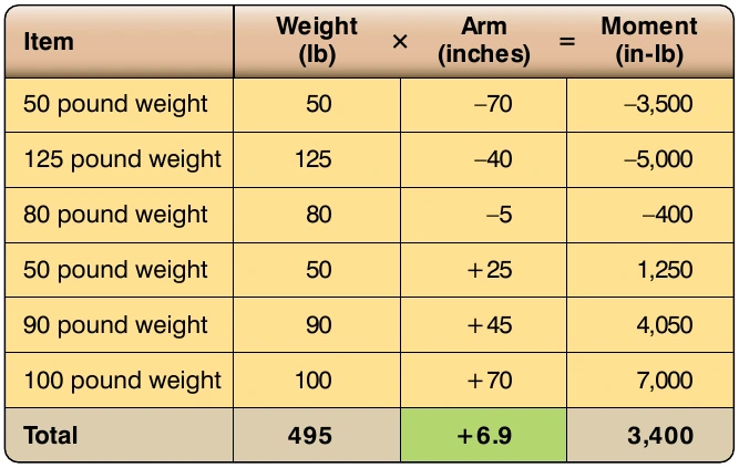
product of the weight and arm. The weight and moment columns are summed, with the CG being equal to the total moment divided by the total weight. The arm column is not summed. The number appearing at the bottom of that column is the CG. The calculation is shown in Figure 6-7.
For the calculation in Figure 6-7, the total moment is 52,900 in-lb, and the total weight is 495 lb. The CG is calculated as follows:
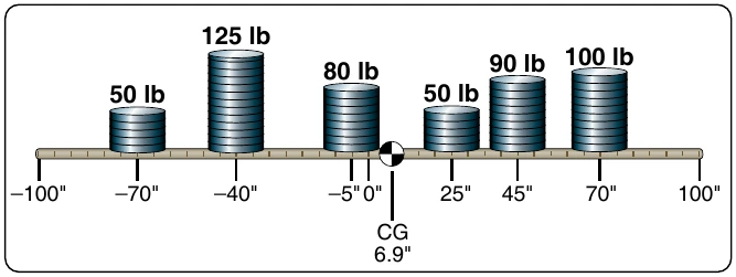
An interesting characteristic exists for the problem in Figure 6-6 and the table showing the CG calculation. If the datum (zero arm) for the object was in the middle of the 200" long plank, with 100" of negative arm to the left and 100" of positive arm to the right, the solution would show the CG to be in the same location. The arm for the CG would not be the same number, but its physical location would be the same. Figures 6-8 and 6-9 show the new calculation.
In Figure 6-8, the CG is 6.9" to the right of the plank’s center. Even though the arm is not the same number, in Figure 6-6 the CG is also 6.9" to the right of center (CG location of 106.9 with the center being 100). Because both problems are the same in these two figures, except for the datum location, the CG must be the same.
The definition for CG states that it is the point about which all the moments are equal. We can prove that the CG for the object in Figure 6-8 is correct by showing that the total moments on either side of this point are equal. Using 6.87 as the CG location for slightly greater accuracy, instead of the rounded off 6.9 number, the moments to the left of the CG are shown in Figure 6-10. The moments to the right of the CG, shown in Figure 6-8, would be as indicated in Figure 6-11. Disregarding the slightly different decimal value, the moment in both previous calculations is 10,651 in-lb. Showing that the moments are equal is a good way of proving that the CG has been properly calculated.
Weight and Balance Data
Before an aircraft can be properly weighed and its EWCG computed, certain information must be known. This information is furnished by the FAA to anyone for every certificated aircraft in the TCDS or Aircraft Specifications. When the design of an aircraft is approved by the FAA, an Approved Type Certificate and TCDS are issued. The TCDS aircraft adheres to them.
Manufacturer-Furnished Information
When an aircraft is initially certificated, its empty weight and EWCG are determined and recorded in the weight and balance record, such as the one in Figure 6-12. An equipment list is furnished with the aircraft that specifies all the required equipment and all equipment approved for installation in the aircraft. The weight and arm of each item is included on the list, and all equipment installed when the aircraft left the factory is checked. When an aircraft mechanic or repairman adds or removes any item on the equipment list, they must change the weight and balance record to indicate the new empty weight and EWCG, and the equipment list is revised to show what is installed.
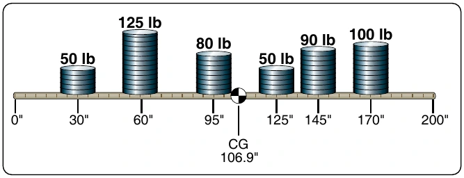
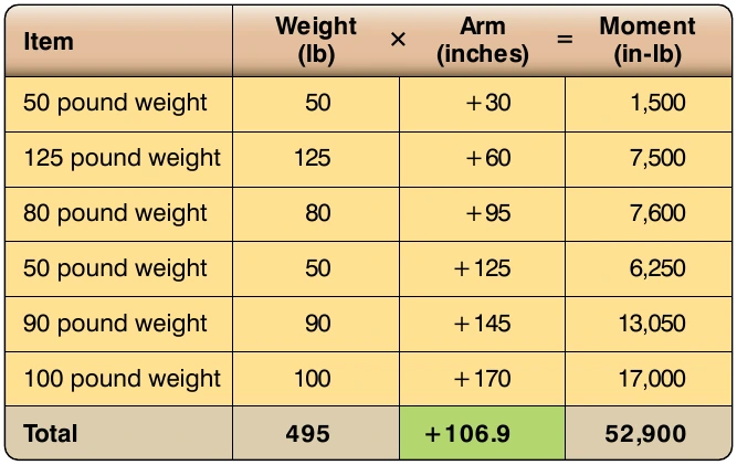
Figure 6-13 is an excerpt from a comprehensive equipment list that includes all the items of equipment approved for this model of aircraft. The Pilot’s Operating Handbook (POH) or Airplane Flight Manual (AFM) for each individual aircraft includes an aircraft specific equipment list of the items from this master list. When any item is added to or removed from the aircraft, its weight and arm are determined in the equipment list and used to update the weight and balance record. The POH/AFM also contains CG moment envelopes and loading graphs.
Figures 6-14 through 6-16 shows a TCDS for a Piper twin-engine airplane known as the Seneca (PA-34-200). The main headings for the information contained in a TCDS are included, but much of the information contained under these headings has been removed if it did not directly pertain to weight and balance. Information on only one model of Seneca is shown, because to show all the different models would make the document excessively long. The portion of the TCDS that has the most direct application to weight and balance is highlighted in yellow.
Some of the important weight and balance information found in a TCDS is as follows:
- Engine
- CG range
- Maximum weight
- Number of seats
- Baggage capacity
- Fuel capacity
- Oil capacity
- Datum information
- Leveling means