
Chapter 3
Induction & Exhaust Systems
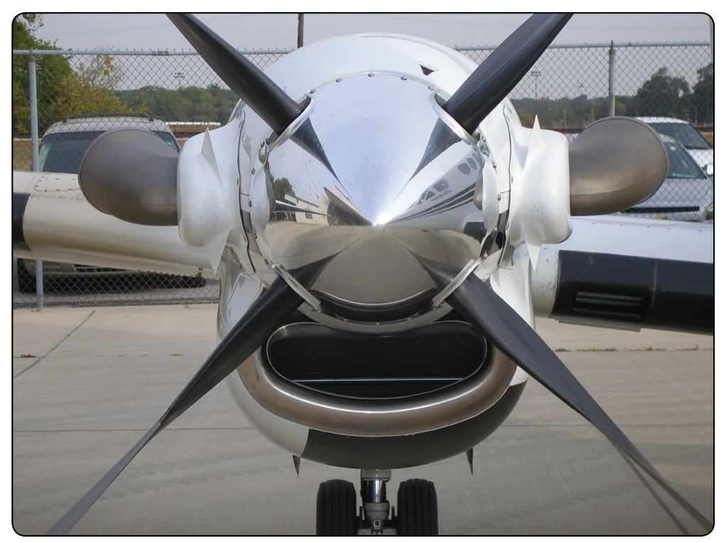
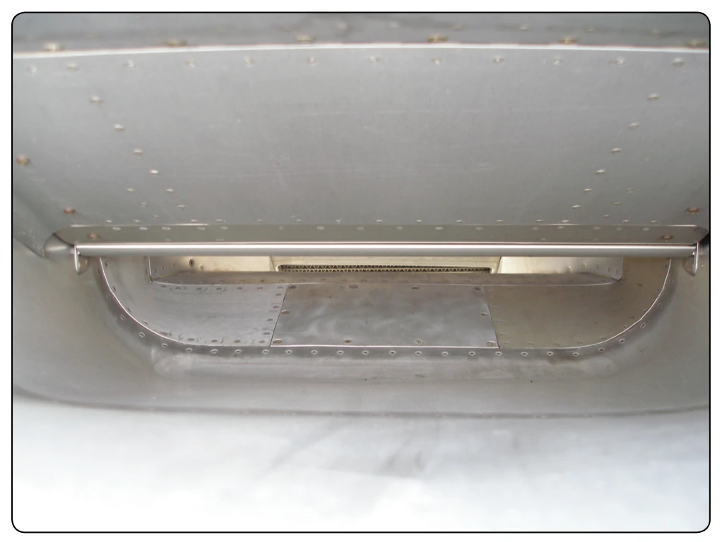
The air inlet on a turboprop is more of a problem than some other gas turbine engines because the propeller drive shaft, the hub, and the spinner must be considered in addition to other inlet design factors. The ducted arrangement is generally considered the best inlet design of the turboprop engine as far as airflow and aerodynamic characteristics are concerned. [Figure 3-32] The inlet for many types of turboprops are anti-iced by using electrical elements in the lip opening of the intake. Ducting either part of the engine or nacelle directs the airflow to the intake of the engine. Deflector doors are sometimes used to deflect ice or dirt away from the intake. [Figure 3-33] The air then passes through a screen and into the engine on some models. A conical spinner, which does not allow ice to build up on the surface, is sometimes used with turboprop and turbofan engines. In either event, the arrangement of the spinner and the inlet duct plays an important function in the operation and performance of the engine.
Turbofan Engine Inlet Sections
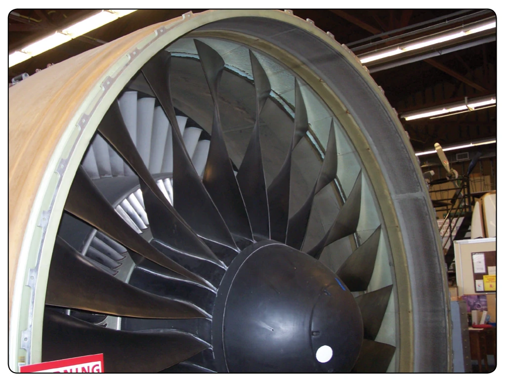
High-bypass turbofan engines are usually constructed with the fan at the forward end of the compressor. A typical turbofan intake section is shown in Figure 3-34. Sometimes, the inlet cowl is bolted to the front of the engine and provides the airflow path into the engine. In dual compressor (dual spool) engines, the fan is integral with the relatively slowturning, low-pressure compressor, which allows the fan
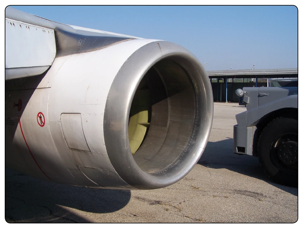
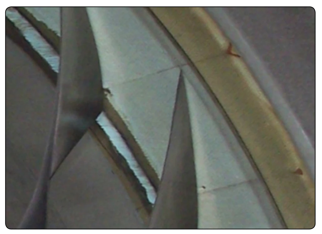
blades to rotate at low tip speed for best fan efficiency. The fan permits the use of a conventional air inlet duct, resulting in low inlet duct loss. The fan reduces engine damage from ingested foreign material because much of any material that may be ingested is thrown radially outward and passes through the fan discharge rather than through the core of the engine. Warm bleed air is drawn from the engine and circulated on the inside of the inlet lip for anti-icing. The fan hub or spinner is either heated by warm air or is conical as mentioned earlier. Inside the inlet by the fan blade tips is an abraidable rub strip that allows the fan blades to rub for short times due to flightpath changes. [Figure 3-35] Also, inside the inlet are sound-reducing materials to lower the noise generated by the fan.
The fan on high-bypass engines consists of one stage of rotating blades and stationary vanes that can range in diameter from less than 84 inches to more than 112 inches. [Figure 3-36] The fan blades are either hollow titanium or composite materials. The air accelerated by the outer part of
the fan blades forms a secondary airstream, which is ducted overboard without passing through the main engine. This secondary air (fan flow) produces 80 percent of the thrust in high-bypass engines. The air that passes through the inner part of the fan blades becomes the primary airstream (core flow) through the engine itself. [Figure 3-36]
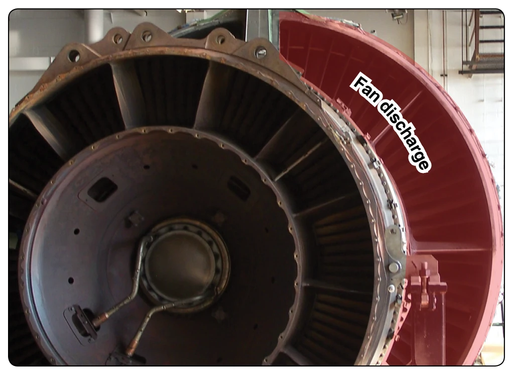
The air from the fan exhaust, which is ducted overboard, may be discharged in either of two ways:
- To the outside air through short ducts (dual exhaust nozzles) directly behind the fan. [Figure 3-37]
- Ducted fan, which uses closed ducts all the way to the rear of the engine, where it is exhausted to the outside air through a mixed exhaust nozzle. This type engine is called a ducted fan and the core airflow and fan airflow mix in a common exhaust nozzle.
Reciprocating Engine Exhaust Systems
The reciprocating engine exhaust system is fundamentally a scavenging system that collects and disposes of the high temperature, noxious gases being discharged by the engine. Its main function is to dispose of the gases with complete safety to the airframe and the occupants of the aircraft. The exhaust system can perform many useful functions, but its first duty is to provide protection against the potentially destructive action of the exhaust gases. Modern exhaust systems, though comparatively light, adequately resist high temperatures, corrosion, and vibration to provide long, trouble-free operation with minimum maintenance.
There are two general types of exhaust systems in use on reciprocating aircraft engines: the short stack (open) system and the collector system. The short stack system is generally used on nonsupercharged engines and low-powered engines where noise level is not too objectionable. The collector system is used on most large nonsupercharged engines and on all turbosupercharged engines and installations on which it would improve nacelle streamlining or provide easier maintenance in the nacelle area. On turbosupercharged engines, the exhaust gases must be collected to drive the turbine compressor of the supercharger. Such systems have individual exhaust headers that empty into a common collector ring with only one outlet. From this outlet, the hot exhaust gas is routed via a tailpipe to the turbosupercharger that drives the turbine. Although the collector system raises the back pressure of the exhaust system, the gain in horsepower from turbosupercharging more than offsets the loss in horsepower that results from increased back pressure. The short stack system is relatively simple, and its removal and installation consists essentially of removing and installing the hold-down nuts and clamps. Short stack systems have limited use on most modern aircraft.
In Figure 3-38, the location of typical collector exhaust
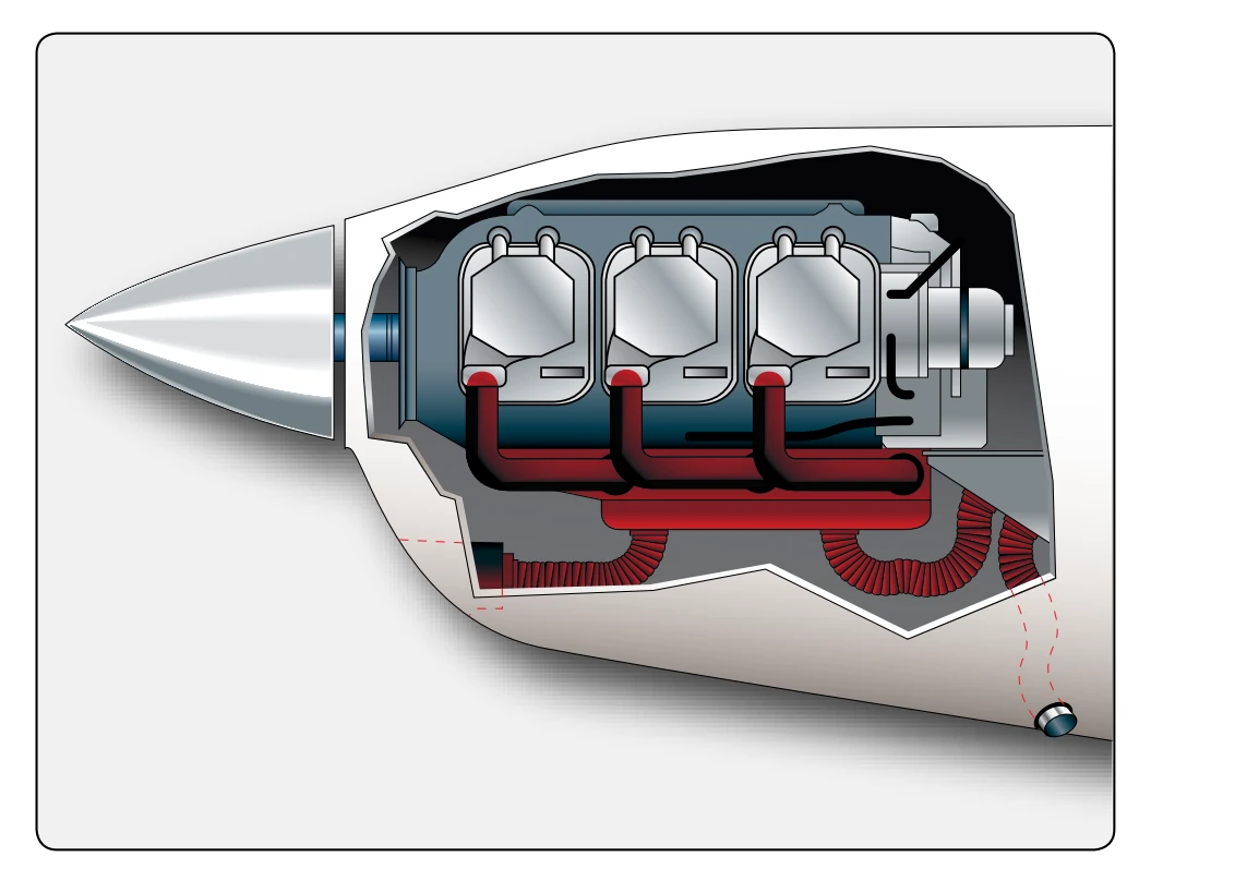
system components of a horizontally opposed engine is shown in a side view. The exhaust system in this installation consists of a down-stack from each cylinder, an exhaust collector tube on each side of the engine, and an exhaust ejector assembly protruding aft and down from each side of the firewall. The down-stacks are connected to the cylinders with high temperature locknuts and secured to the exhaust collector tube by ring clamps. A cabin heater exhaust shroud is installed around each collector tube. [Figure 3-39]