
Chapter 3
Induction & Exhaust Systems
Variable Absolute Pressure Controller (VAPC)
The VAPC contains an oil control valve similar to the other
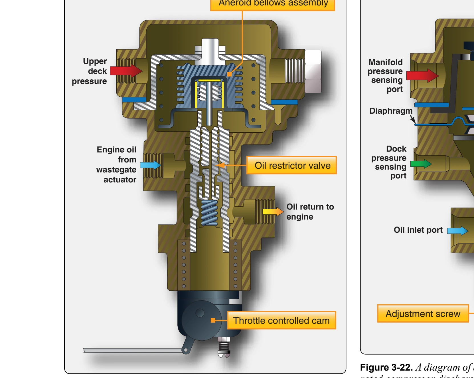
rises, the controller poppet opens and decreases turbocharger controllers that were discussed. [Figure 3-21] The oil restrictor is actuated by an aneroid bellows that is referenced to upper deck pressure. A cam connected to the throttle mechanism applies pressure to the restrictor valve and aneroid. As the throttle is opened to greater values, the cam applies a greater pressure to the aneroid. This increases the amount of upper deck pressure necessary to compress the aneroid and thereby open the oil restrictor valve. This means that the scheduled absolute value of upper deck pressure that is required to overcome the aneroid is variable by throttle position. As the throttle is opened wide, the manifold pressure and upper deck pressure requirements greatly increase.
Sloped Controller
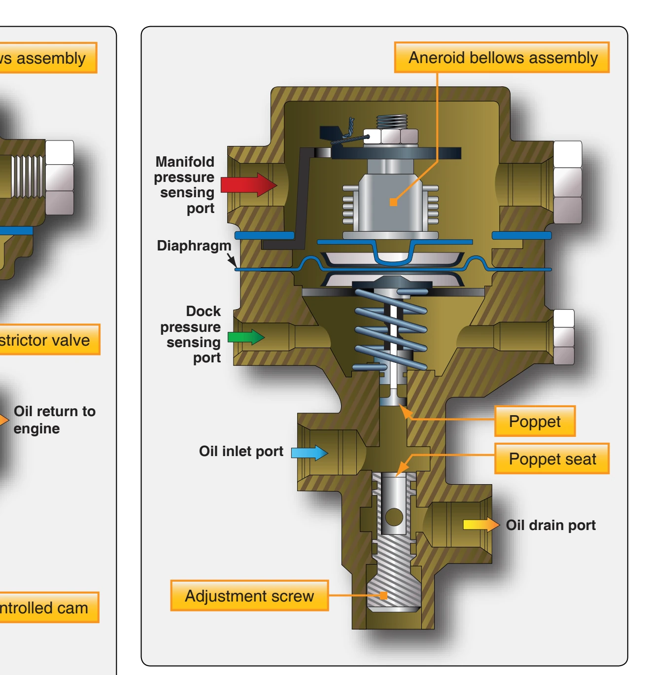
The sloped controller is designed to maintain the rated compressor discharge pressure at wide-open throttle and to reduce this pressure at part throttle settings. [Figure 3-22] A diaphragm, coupled with a spring-supported bellows for absolute pressure reference, is exposed to deck pressure and intake manifold pressure through ports located before and after the throttle, respectively. This arrangement constantly monitors deck pressure and the pressure differential between the deck and manifold pressure due to a partially closed throttle. If either deck pressure or throttle differential pressure discharge (deck) pressure. The sloped controller is more sensitive to the throttle differential pressure than to deck pressure, thereby accomplishing deck pressure reduction as the throttle is closed.
Absolute Pressure Controller
One device used to control the speed and output of the turbocharger, but controls the system only at maximum output, is the absolute pressure controller. The absolute pressure controller contains an aneroid bellows that is referenced to upper deck pressure. It operates the waste gate, which diverts, more or less, exhaust gas over the turbine. As an absolute pressure setting is reached, it bypasses oil, and relieves the pressure on the waste gate actuator. This allows the absolute pressure controller to control the maximum turbocharger compressor discharge pressure. The turbocharger is completely automatic, requiring no pilot action up to the critical altitude.
Turbocharger System Troubleshooting
Figure 3-23 includes some of the most common turbocharger system malfunctions together with their cause and repair. These troubleshooting procedures are presented as a guide only and should not be substituted for applicable
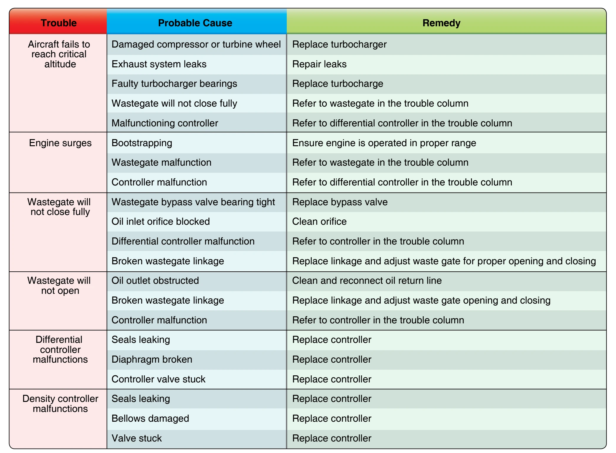
manufacturer’s instructions or troubleshooting procedures.
Turbine Engine Inlet Systems
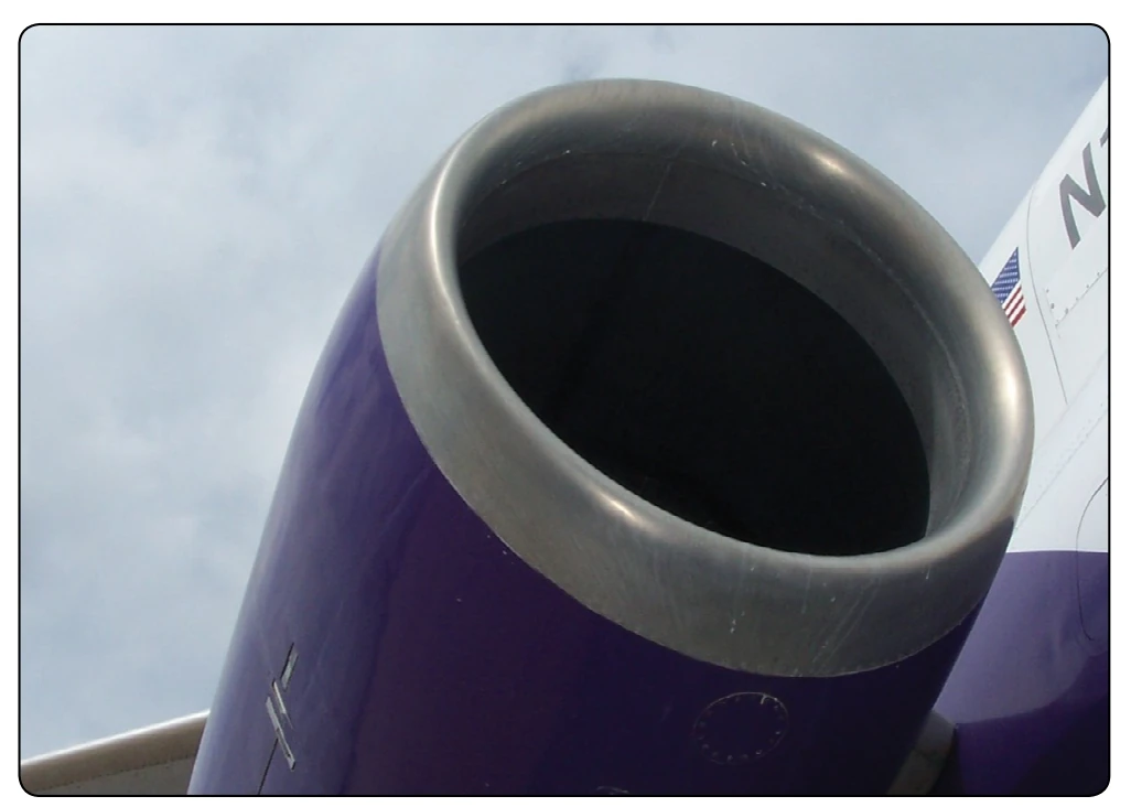
The engine inlet of a turbine engine is designed to provide a relatively distortion-free flow of air, in the required quantity, to the inlet of the compressor. [Figure 3-24] Many engines use inlet guide vanes (IGV) to help straighten the airflow and direct it into the first stages of the compressor. A uniform and steady airflow is necessary to avoid compressor stall (airflow tends to stop or reverse direction of flow) and excessive internal engine temperatures in the turbine section. Normally, the air-inlet duct is considered an airframe part and not a part of the engine. However, the duct is very important to the engine’s overall performance and the engine’s ability to produce an optimum amount of thrust.
A gas turbine engine consumes considerable more airflow than a reciprocating engine. The air entrance passage is correspondingly larger. Furthermore, it is more critical in determining engine and aircraft performance, especially at high airspeeds. Inefficiencies of the inlet duct result in successively magnified losses through other components of the engine. The inlet varies according to the type of turbine engine. Small turboprop and turboshaft engines have a lower airflow than large turbofan engines which require a completely different type of inlet. Many turboprop, auxiliary power units, and turboshaft engines use screens that cover the inlet to prevent foreign object damage (FOD).
As aircraft speed increases, thrust tends to decrease somewhat; as the aircraft speed reaches a certain point, ram recovery compensates for the losses caused by the increases in speed. The inlet must be able to recover as much of the total pressure of the free airstream as possible. As air molecules are trapped and begin to be compressed in the inlet, much of the pressure loss is recovered. This added pressure at the inlet of the engine increases the pressure and airflow to the engine. This is known as “ram recovery” or “total pressure recovery.” The inlet duct must uniformly deliver air to the compressor inlet with as little turbulence and pressure variation as possible. The engine inlet duct must also hold the drag effect on the aircraft to a minimum.
Air pressure drop in the engine inlet is caused by the friction of the air along both sides of the duct and by the bends in the duct system. Smooth flow depends upon keeping the amount of turbulence to a minimum as the air enters the duct. On engines with low flow rates, turning the airflow allows the engine nacelle to be smaller and have less drag. On turbofan engines, the duct must have a sufficiently straight section to ensure smooth, even airflow because of the high airflows. The choice of configuration of the entrance to the duct is dictated by the location of the engine within the aircraft and the airspeed, altitude, and attitude at which the aircraft is designed to operate. To accomplish this, inlet ducts are designed to function as diffusers with a divergent shape, decreasing the velocity and increasing the static pressure of the air passing through them.