
Chapter 4
Engine Ignition & Electrical Systems
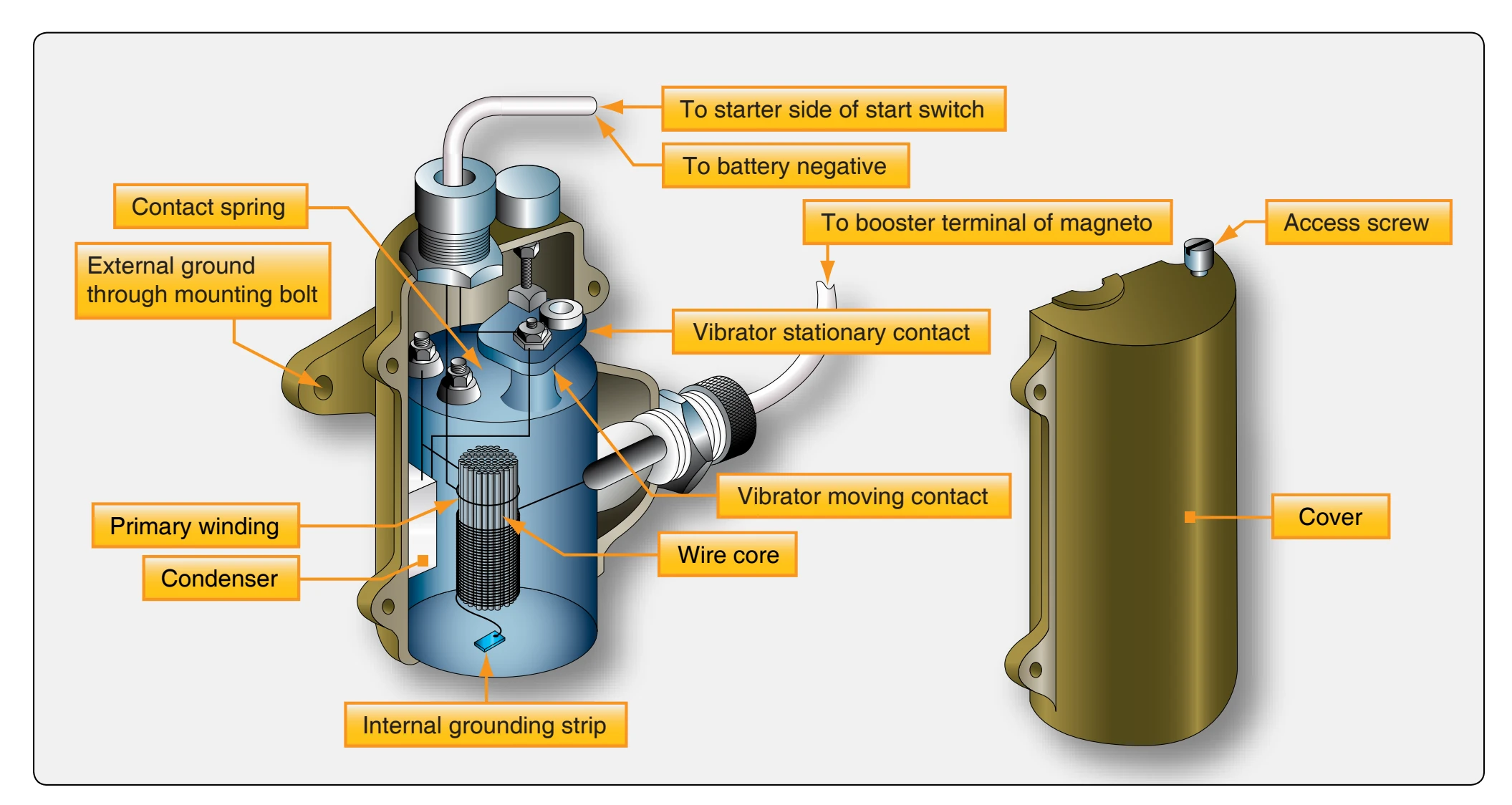
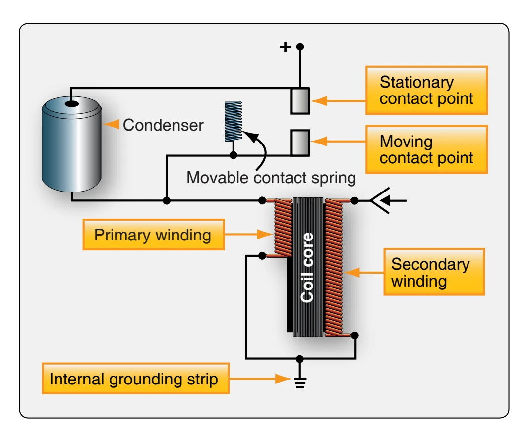
The condenser, which is connected across the contact points, has an important function in this circuit. [Figure 4-32] As current flow in the primary coil is interrupted by the opening of the contact points, the high self-induced voltage that accompanies each collapse of the primary magnetic field surges into the condenser. Without a condenser, an arc would jump across the points with each collapse of the magnetic field. This would burn and pit the contact points and greatly reduce the voltage output of the booster coil. The booster coil generates a pulsating DC in the primary winding that induces a high-voltage spark in the secondary windings of the booster coil.
Impulse Coupling
Many opposed reciprocating engines are equipped with an impulse coupling as the auxiliary starting system. An impulse coupling gives one of the magnetos attached to the
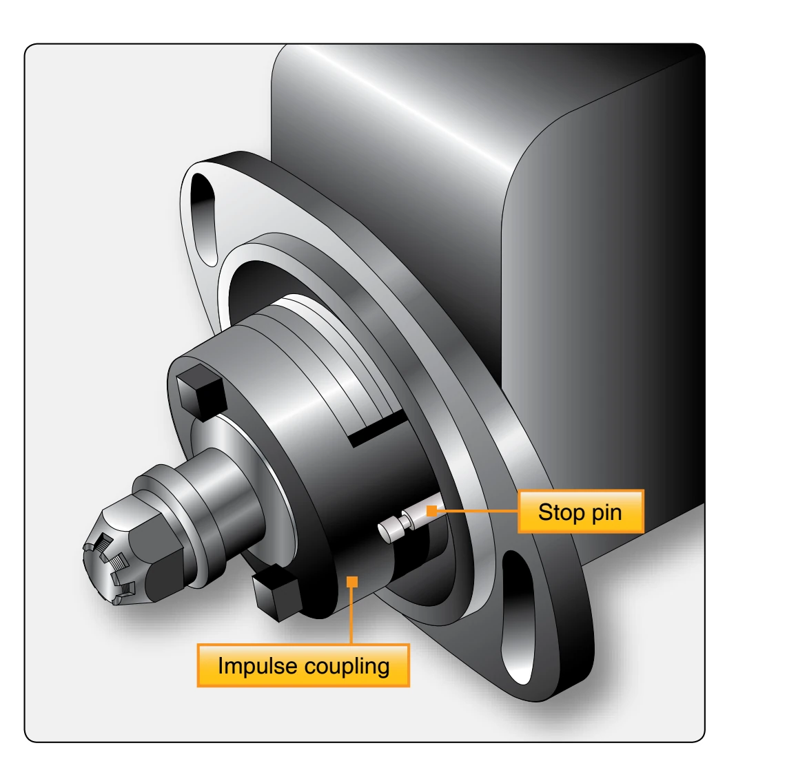
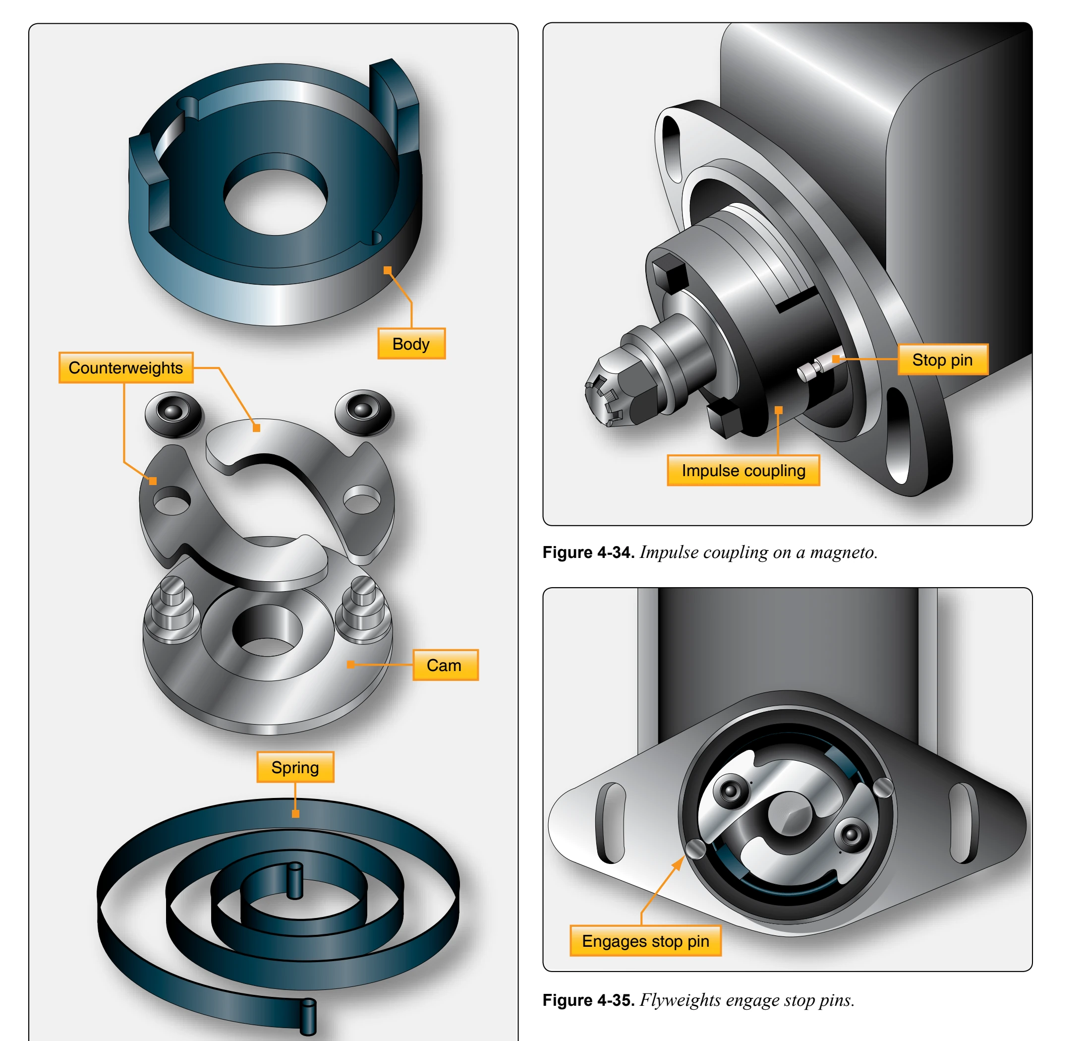
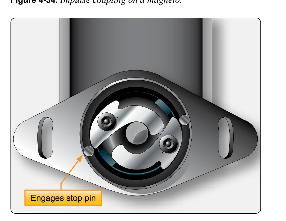
engine, generally the left, a brief acceleration, that produces an intense spark for starting. This device consists of a cam and flyweight assembly, spring, and a body assembly. [Figure 4-33] The assembled impulse coupling is shown installed on a typical magneto in Figure 4-34.
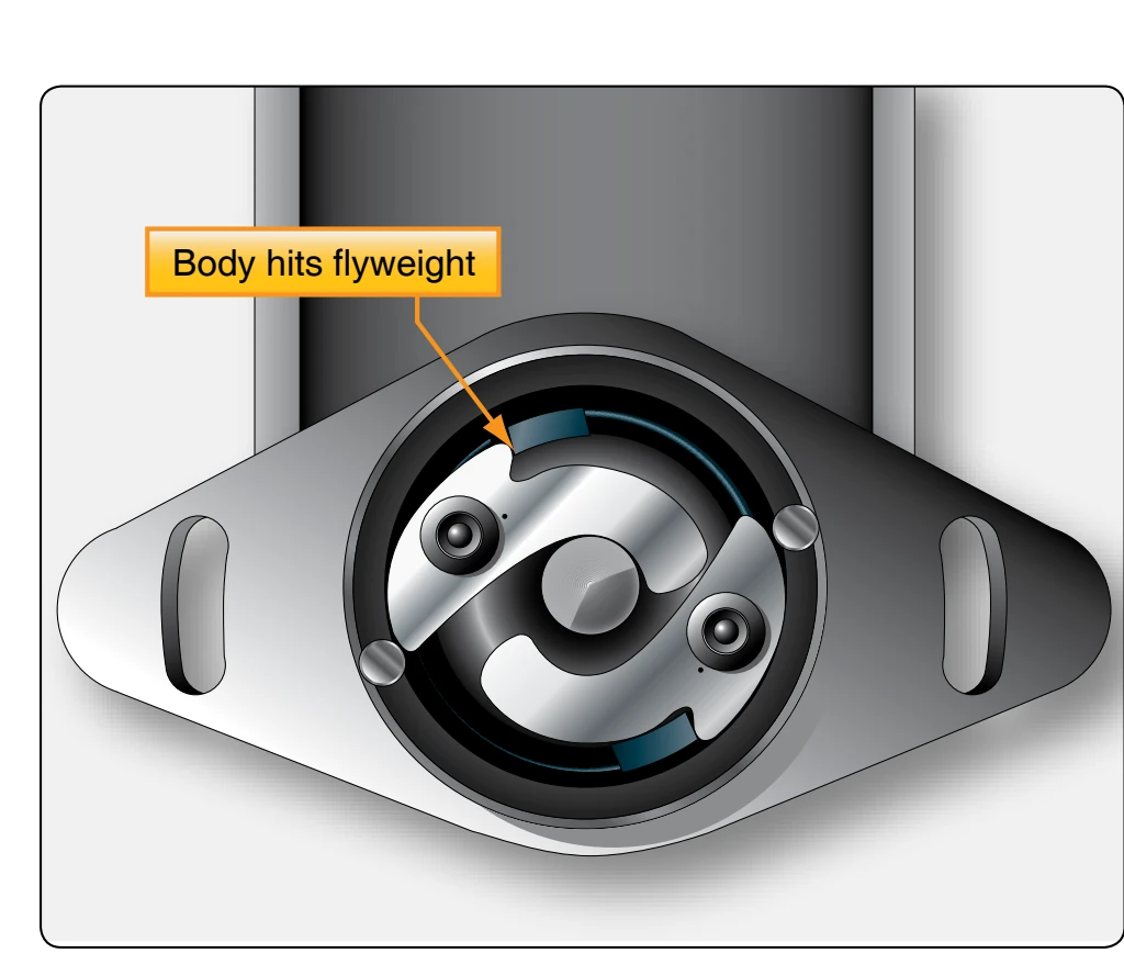
The magneto is flexibly connected through the impulse coupling by means of the spring so that at low speed the magneto is temporarily held. [Figure 4-35] The flyweight, because of slow rotation, catches on a stud or stop pins, and the magneto spring is wound as the engine continues to turn. The engine continues to rotate until the piston of the cylinder to be fired reaches approximately a top dead center position. At this point, the magneto flyweight contacts the body of the impulse coupling and is released. The spring kicks back to its original position, resulting in a quick twist of the rotating magnet of the magneto. [Figure 4-36] This, being equivalent to high-speed magneto rotation, produces a spark that jumps the gap at the spark plug electrodes. The impulse coupling has two functions: rotating the magneto fast enough to produce a good spark and retarding the timing of the spark during the start cycle. After the engine is started and the magneto reaches a speed at which it furnishes sufficient current, the flyweights in the impulse coupling fly outward due to centrifugal force or rapid rotation. This action prevents the two flyweight coupling members from contact with the stop pin. That makes it a solid unit, returning the magneto to a normal timing position relative to the engine. The presence of an impulse coupling is identified by a sharp clicking noise as the crankshaft is turned at starter cranking speed past top center on each cylinder.
A problem that can arise from impulse couplings is that the flyweights can become magnetized and not engage the stop pins. Congealed oil or sludge on the flyweights during cold weather may produce the same results. This prevents the flyweight weights from engaging the stop pins, which results in no starting spark being produced. Wear can cause problems with impulse couplings. They should be inspected and any maintenance should be performed as set forth by the manufacturer. Another disadvantage of the impulse coupling is that it can produce only one spark for each firing cycle of the cylinder. This is a disadvantage, especially during
enclosed in a metal case.
The starting vibrator, unlike the booster coil, does not adverse starting conditions. Even with these disadvantages, the impulse coupling is still in wide use.
High-Tension Retard Breaker Vibrator
To provide for more spark power during the starting cycle, the shower of sparks system was developed, which provides several sparks at the spark plug electrodes during starting. The starting vibrator, or shower of sparks, consists essentially of an electrically operated vibrator, a condenser, and a relay. [Figure 4-37] These units are mounted on a base plate and produce the high ignition voltage within itself. The function of this starting vibrator is to change the DC of the battery into a pulsating DC and deliver it to the primary coil of the magneto. Closing the ignition switch energizes the starter solenoid and causes the engine to rotate. At the same time, current also flows through the vibrator coil and its contact points. Current flow in the vibrator coil sets up a magnetic field that attracts and opens the vibrator points. When the vibrator points open, current flow in the coil stops, and the magnetic field that attracted the movable vibrator contact point disappears. This allows the vibrator points to close and
again permits battery current to flow in the vibrator coil. This completes a cycle of operation. The cycle, however, occurs many times per second, so rapidly that the vibrator points produce an audible buzz.
Each time the vibrator points close, current flows to the magneto as a pulsating DC. Since this current is being interrupted many times per second, the resulting magnetic field is building and collapsing across the primary and secondary coils of the magneto many times per second. The rapid successions of separate voltages induced in the secondary coil produces a shower of sparks across the selected spark plug air gap.
The retard breaker magneto and starting vibrator system is used as part of the high-tension starting system on many types of aircraft. Designed for four- and six-cylinder ignition systems, the retard breaker magneto eliminates the need for the impulse coupling in light aircraft. This system uses an additional breaker to obtain retarded sparks for starting. The starting vibrator is also adaptable to many helicopter ignition systems. A schematic diagram of an ignition system using the retard breaker magneto and starting vibrator concept is shown in Figure 4-37.
With the magneto switch in the both position and the starter switch S1 in the on position, starter solenoid L3 and coil L1 are energized, closing relay contacts R4, R1, R2, and R3. R3 connects the right magneto to ground, keeping it inoperative during starting operation. Electrical current flows from the battery through R1, vibrator points V1, coil L2, through both the retard breaker points, through R2, and the main breaker points of the left magneto to ground.