
Chapter 4
Engine Ignition & Electrical Systems
The energized coil L2 opens vibrator points V1, interrupting the current flow through L2. The magnetic field about L2 collapses, and vibrator points V1 close again. Once more,
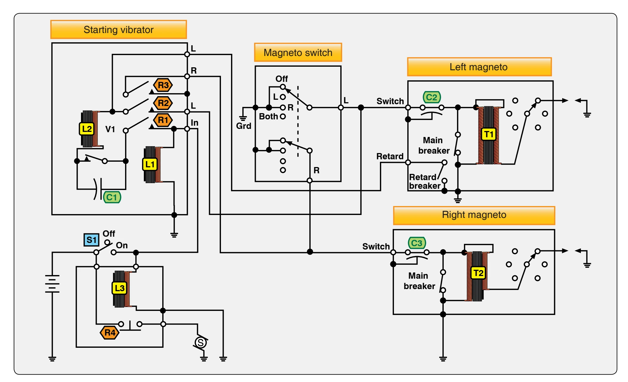
current flows through L2, and again V1 vibrator points open. This process is repeated continuously, and the interrupted battery current flows to ground through the main and retard breaker points of the left magneto.
Since relay R4 is closed, the starter is energized and the engine crankshaft is rotated. When the engine reaches its normal advance firing position, the main breaker points of the left magneto begin to open. The interrupted surges of current from the vibrator can still find a path to ground through the retard breaker points, which do not open until the retarded firing position of the engine is reached. At this point in crankshaft travel, the retard points open. Since the main breaker points are still open, the magneto primary coil is no longer shorted, and current produces a magnetic field around T1.
Each time the vibrator points V1 open, current flow through V1 is interrupted. The collapsing field about T1 cuts through the magneto coil secondary and induces a high-voltage surge of energy used to fire the spark plug. Since the V1 points are opening and closing rapidly and continuously, a shower of sparks is furnished to the cylinders when both the main and retard breaker points are open.
After the engine begins to accelerate, the manual starter switch is released, causing L1 and L3 to become deenergized. This action causes both the vibrator and retard breaker circuits to become inoperative. It also opens relay contact R3, which removes the ground from the right magneto. Both magnetos now fire at the normal running advanced degree position of crankshaft rotation before top dead center piston position.
Low-Tension Retard Breaker Vibrator
This system, which is in limited use, is designed for light aircraft reciprocating engines. A typical system consists of a retard breaker magneto, a single breaker magneto, a starting vibrator, transformer coils, and a starter and ignition switch. [Figure 4-38]
To operate the system, place the starter switch S3 in the on position. This energizes starter solenoid L3 and coil L1, closing relay contacts R1, R2, R3, and R4. With the magneto switch in the L position, current flows through R1, the vibrator points, L2, R2, and through the main breaker points to ground. Current also flows through R3 and the retard breaker points to ground. Current through L2 builds up a magnetic field that opens the vibrator points. Then, the current stops flowing through L2, reclosing the points. These surges of current flow through both the retard and main breaker points to ground.
Since the starter switch is closed, the engine crankshaft is turning. When it has turned to the normal advance or running ignition position, the main breaker points of the magneto
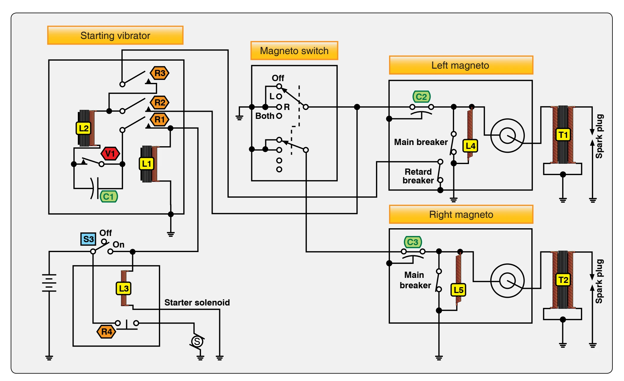
open. However, current still flows to ground through the closed retard breaker points. As the engine continues to turn, the retard ignition position is reached, and the retard breaker points open. Since the main breaker points are still open, current must flow to ground through coil L4, producing a magnetic field around the coil L4.
As the engine continues to turn, the vibrator breaker points open, collapsing the L4 magnetic field through T1 primary, inducing a high-voltage in the secondary of T1 to fire the spark plug.
When the engine fires, the starter switch is released, deenergizing L1 and L3. This opens the vibrator circuit and retard breaker points circuit. The ignition switch is then turned to the both position, permitting the right magneto to operate in time with the left magneto.
Spark Plugs
The function of the spark plug in an ignition system is to conduct a short impulse of high-voltage current through the wall of the combustion chamber. Inside the combustion chamber, it provides an air gap across which the impulse can produce an electric spark to ignite the air-fuel charge. While the aircraft spark plug is simple in construction and operation, it can be the cause of malfunctions in aircraft engines. Despite this fact, spark plugs provide a great deal of trouble-free operation when properly maintained and when correct engine operating procedures are practiced.
Spark plugs operate at extreme temperatures, electrical pressures, and very high cylinder pressures. A cylinder of an engine operating at 2,100 rpm must produce approximately 17 separate and distinct high-voltage sparks that bridge the air gap of a single spark plug each second. This would appear as a continuous spark across the spark plug electrodes at temperatures of over 3,000 °F. At the same time, the spark plug is subjected to gas pressures as high as 2,000 pounds per square inch (psi) and electrical pressure as high as 20,000 volts. Given the extremes that spark plugs must operate under, and the fact that the engine loses power if one spark does not occur correctly, proper function of a spark plug in the operation of the engine is imperative.
The three main components of a spark plug are the electrode, insulator, and outer shell. [Figure 4-39] The outer shell, threaded to fit into the cylinder, is usually made of finely machined steel and is often plated to prevent corrosion from engine gases and possible thread seizure. Close-tolerance screw threads and a copper gasket prevent cylinder gas pressure from escaping around the plug. Pressure that might escape through the plug is retained by inner seals between the outer metal shell and the insulator, and between the insulator
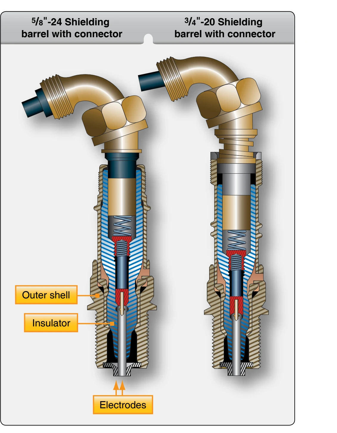
and the center electrode assembly. The other end is threaded to receive the ignition lead from the magneto. All-weather plugs form a seal between the lead and the plug that is water proof to prevent moisture from entering this connection.