
Chapter 4
Engine Ignition & Electrical Systems
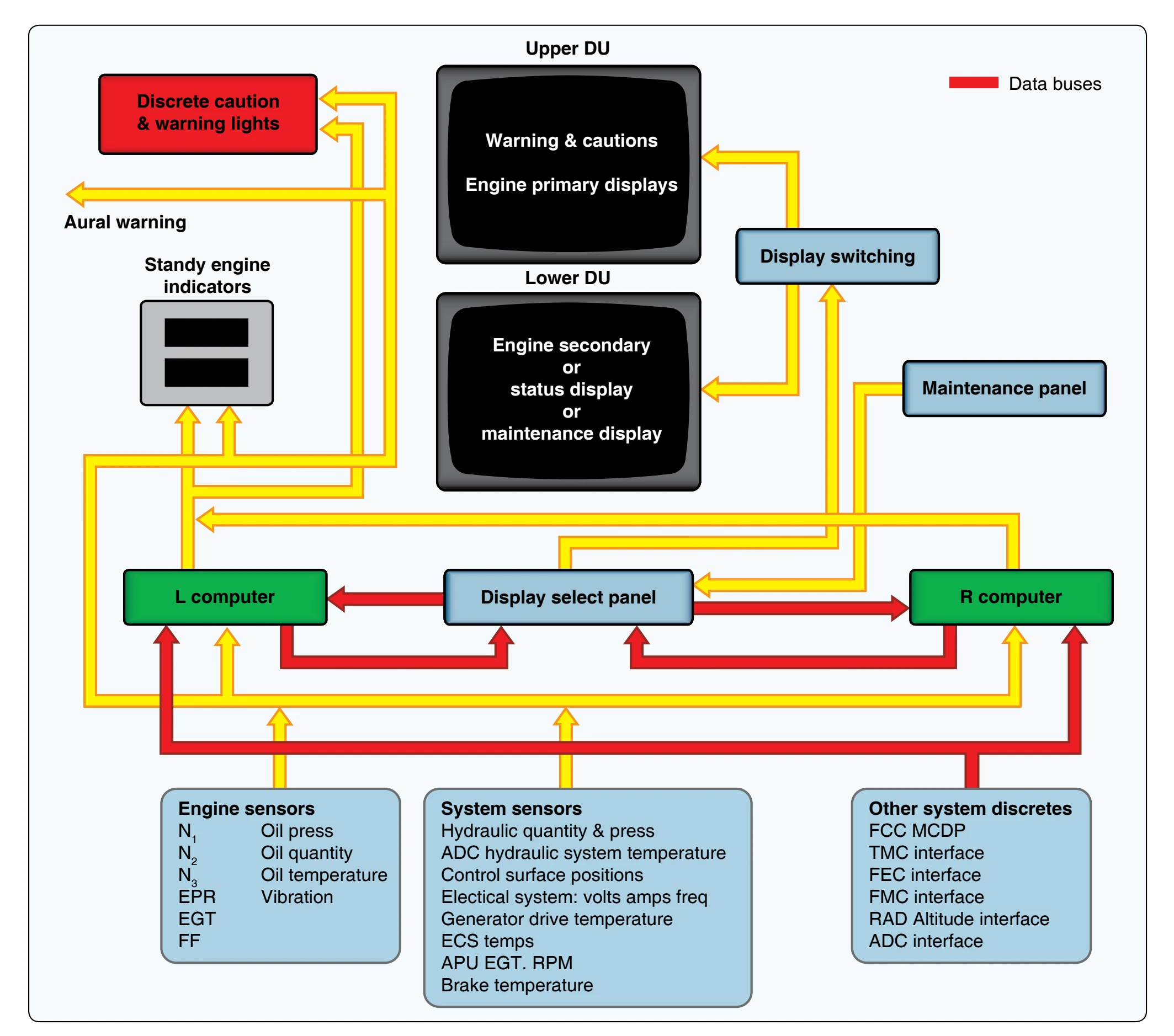
EICAS provides full time primary engine parameters (EPR, N1, EGT) on the top, primary monitor. Advisories and
and nonengine system status are displayed on the bottom screen. The lower screen is also used for maintenance diagnosis when the aircraft is on the ground. Color coding is used, as well as message prioritizing.
The display select panel allows the pilot to choose which computer is actively supplying information. It also controls the display of secondary engine information and system status displays on the lower monitor. EICAS has a unique feature that automatically records the parameters of a failure event to be regarded afterwards by maintenance personnel. Pilots that suspect a problem may be occurring during flight can press the event record button on the display select panel. This also records the parameters for that flight period to be studied later by maintenance. Hydraulic, electrical, environmental, performance, and APU data are examples of what may be recorded.
EICAS uses BITE for systems and components. A maintenance panel is included for technicians. From this panel, when the aircraft is on the ground, push-button switches display information pertinent to various systems for analysis. [Figure 4-30]
Auxiliary Ignition Units
During engine starting, the output of a magneto is low because the cranking speed of the engine is low. This is understandable when the factors that determine the amount of voltage induced in a circuit are considered.
To increase the value of an induced voltage, the strength of the magnetic field must be increased by using a stronger magnet, by increasing the number of turns in the coil, or by increasing the rate of relative motion between the magnet and the conductor.
Since the strength of the rotating magnet and the number of turns in the coil are constant factors in magneto ignition systems, the voltage produced depends upon the speed at which the rotating magnet is turned. When the engine is being cranked for starting, the magnet is rotated at about 80 rpm. Since the value of the induced voltage is so low, a spark may not jump the spark plug gap. To facilitate engine starting, an auxiliary device is connected to the magneto to provide a high ignition voltage.
Ordinarily, such auxiliary ignition units are energized by the battery and connected to the left magneto. Reciprocating engine starting systems normally include one of the following types of auxiliary starting systems: booster coil (older style), starting vibrator (sometimes called shower of sparks), impulse coupling, or electronic ignition systems.
During the starting cycle, the engine is turning very slowly compared to normal speed. The ignition must be retarded or moved back to prevent kickback of the piston trying to
rotate opposite normal rotation. Each starting system has a method of retarding the spark during starting of the engine.
Booster Coil
Used mainly with older radial engine ignition systems, the booster coil assembly consists of two coils wound on a soft iron core, a set of contact points, and a condenser. [Figure 4-31] The booster coil is separate from the magneto and can generate a series of sparks on its own. During the start cycle, these sparks are routed to the trailing finger on the distributor rotor and then to the appropriate cylinder ignition lead. The primary winding has one end grounded at the internal grounding strip and its other end connected to the moving contact point. The stationary contact is fitted with a terminal to which battery voltage is applied when the magneto switch is placed in the start position, or automatically applied when the starter is engaged. The secondary winding, which contains several times as many turns as the primary coil, has one end grounded at the internal grounding strip and the other terminated at a high-tension terminal. The high-tension terminal is connected to an electrode in the distributor by an ignition cable.
Since the regular distributor terminal is grounded through the primary or secondary coil of a high-tension magneto, the high-voltage furnished by the booster coil must be distributed by a separate circuit in the distributor rotor. This is accomplished by using two electrodes in one distributor rotor. The main electrode, or finger, carries the magneto output voltage; the auxiliary electrode or trailing finger, distributes only the output of the booster coil. The auxiliary electrode is always located so that it trails the main electrode, thus retarding the spark during the starting period.
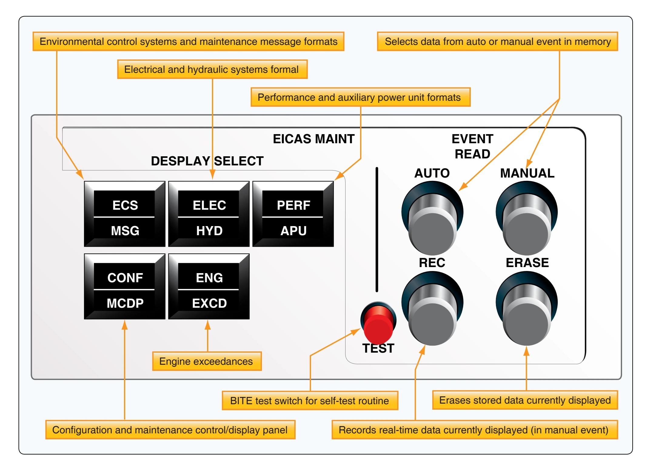
Figure 4-32 illustrates, in schematic form, the booster coil components shown in Figure 4-31. In operation, battery voltage is applied to the positive (+) terminal of the booster coil through the start switch. This causes current to flow through the closed contact points to the primary coil and ground. [Figure 4-32] Current flow through the primary coil sets up a magnetic field about the coil that magnetizes the coil core. As the core is magnetized, it attracts the movable contact point, which is normally held against the stationary contact point by a spring.
As the movable contact point is pulled toward the iron core, the primary circuit is broken, collapsing the magnetic field that extended about the coil core. Since the coil core acts as an electromagnet only when current flows in the primary coil, it loses its magnetism as soon as the primary coil circuit is broken. This permits the action of the spring to close the contact points and again complete the primary coil circuit. This remagnetizes the coil core, and again attracts the movable contact point, which again opens the primary coil circuit. This action causes the movable contact point to vibrate rapidly, as long as the start switch is held in the closed, or on, position. The result of this action is a continuously expanding and collapsing magnetic field that links the secondary coil of the booster coil. With several times as many turns in the secondary as in the primary, the induced voltage that results from lines of force linking the secondary is high enough to furnish ignition for the engine.