
Chapter 4
Engine Ignition & Electrical Systems
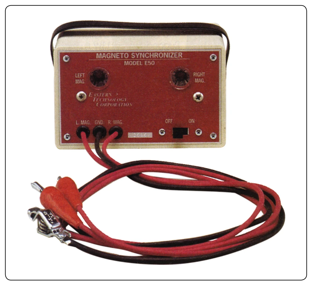
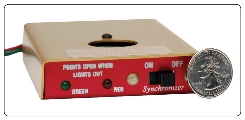
Checking the Internal Timing of a Magneto
When replacing or preparing a magneto for installation, the first concern is with the internal timing of the magneto. For each magneto model, the manufacturer determines how many degrees beyond the neutral position a pole of the rotor magnet should be to obtain the strongest spark at the instant of breaker point separation. This angular displacement from the neutral position, known as the E-gap angle, varies with different magneto models. On one model, a step is cut on the end of the breaker cam to check internal timing of the magneto. When a straightedge is laid along this step and it coincides with the timing marks on the rim of the breaker housing, the magneto rotor is then in the E-gap position, and the breaker contact points should just begin to open.
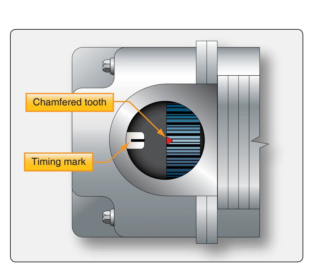
Another method for checking E-gap is to align a timing mark with a pointed chamfered tooth. [Figure 4-50] The breaker points should be just starting to open when these marks line up.
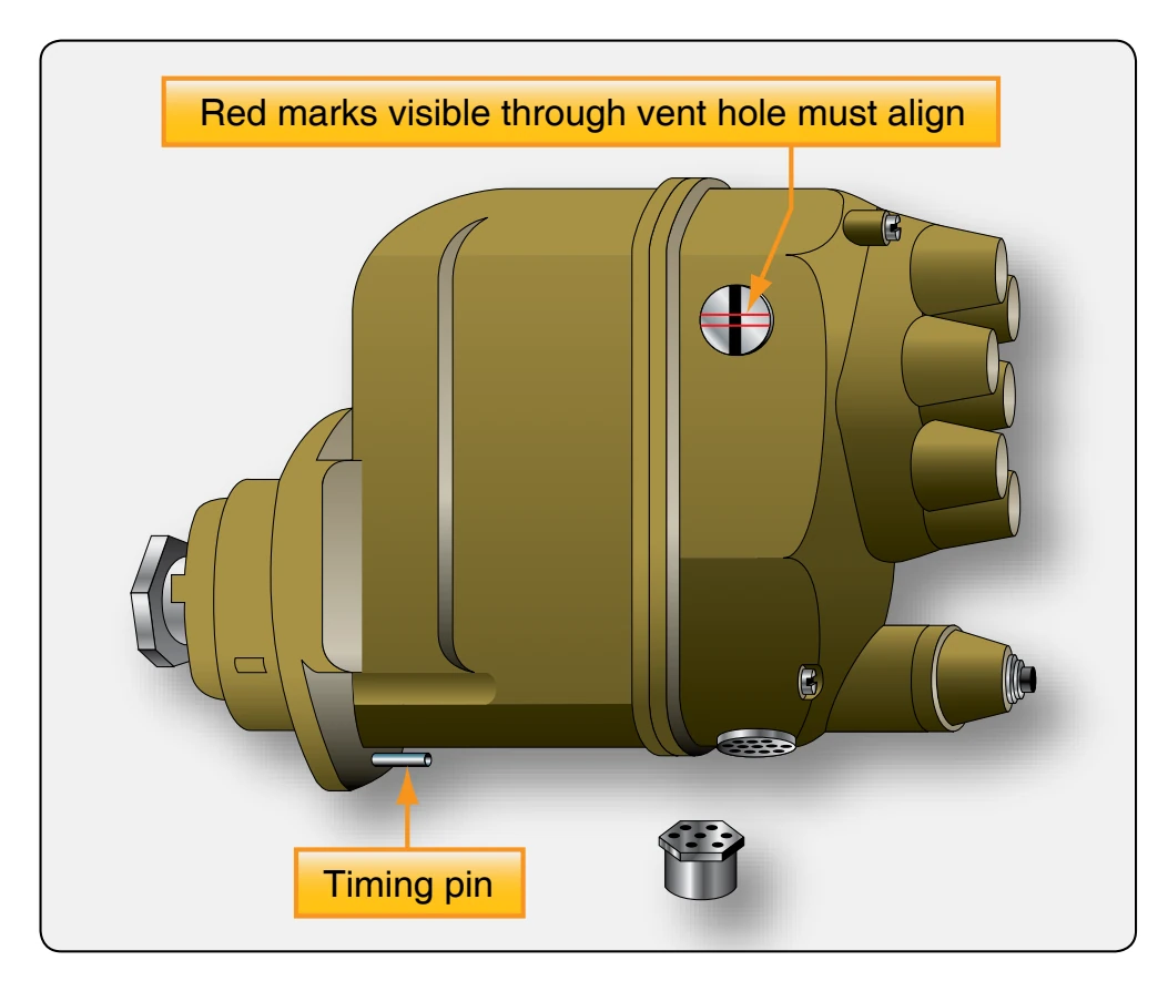
In a third method, the E-gap is correct when a timing pin is in place and red marks visible through a vent hole in the side of the magneto case are aligned. [Figure 4-51] The contact points should be just opening when the rotor is in the position just described.
Bench timing the magneto, or setting the E-gap, involves positioning the magneto rotor at the E-gap position and setting the breaker points to open when the timing lines or marks provided for that purpose are perfectly aligned.
High-Tension Magneto E-Gap Setting (Bench Timing)
The following steps are taken to check and adjust the timing of the breaker points for the S-200 magneto, which does not have timing marks in the breaker compartment:
- Remove the timing inspection plug from the top of the magneto. Turn the rotating magnet in its normal direction of rotation until the painted, chamfered tooth on the distributor gear is approximately in the center of the inspection window. Then, turn the magnet back a few degrees until it is in its neutral position. Because of its magnetism, the rotating magnet holds itself in the neutral position.
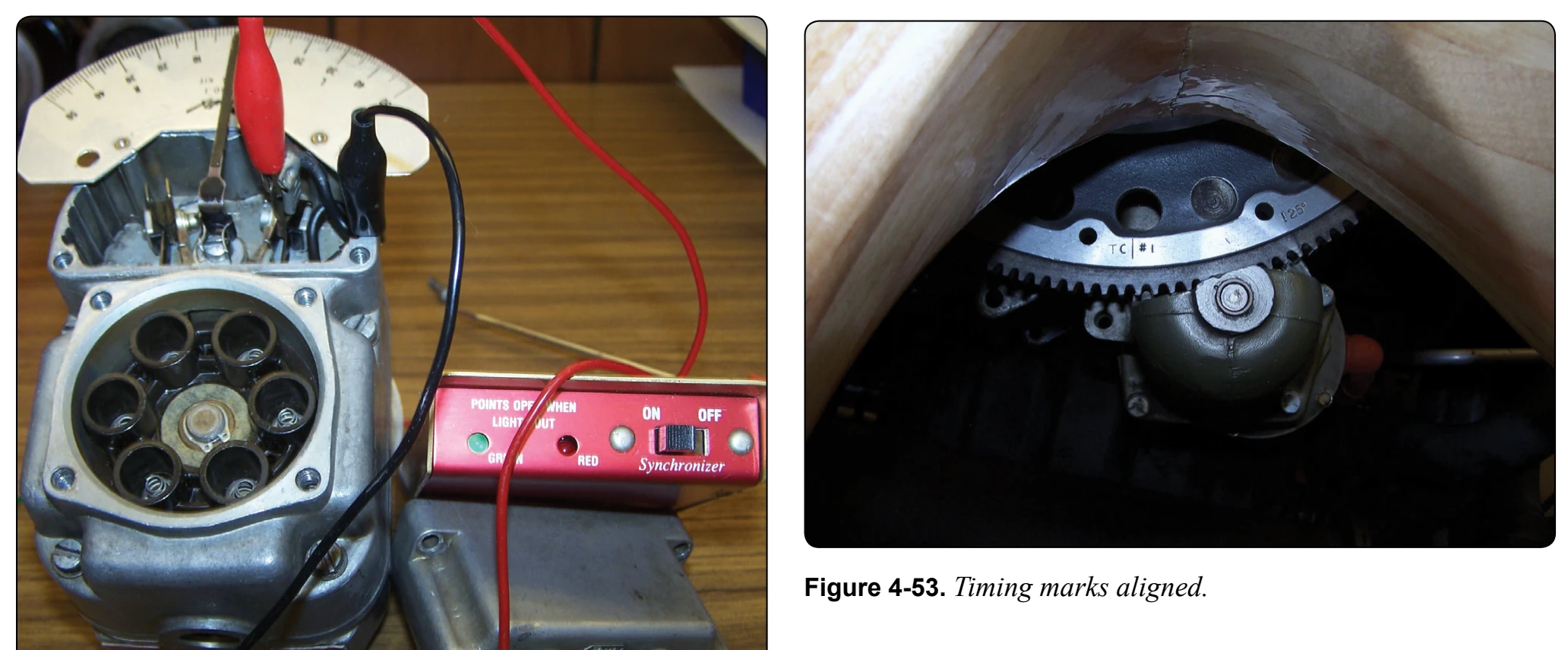
- Install the timing kit and place the pointer in the zero position. [Figure 4-52]
- Connect a suitable timing light across the main breaker points and turn the magnet in its normal direction of rotation 10° as indicated by the pointer. This is the E-gap position. The main breaker points should be adjusted to open at this point.
- Turn the rotating magnet until the cam follower is at the highpoint on the cam lobe, and measure the clearance between the breaker points. This clearance must be 0.018 inch ± 0.006 inch [0.46 millimeter (mm) ± 0.15 mm]. If the breaker point clearance is not within these limits, the points must be adjusted for correct setting. It is then necessary to recheck and readjust the timing for breaker opening. If the breaker points cannot be adjusted to open at the correct time, they should be replaced.
engine drive. It should be installed in the middle of its slotted flange to allow for fine timing of the magneto to the engine. Attach a timing light to both magnetos. With the engine still in the firing position, the magnetos should be timed by
Timing the High-tension Magneto to the Engine
When replacing magnetos on aircraft engines, two factors must be considered:
- The internal timing of the magneto, including breaker point adjustment, which must be correct to obtain maximum potential voltage from the magneto.
- The engine crankshaft position where the spark occurs. The engine is usually timed by using the No. 1 cylinder on the compression stroke.
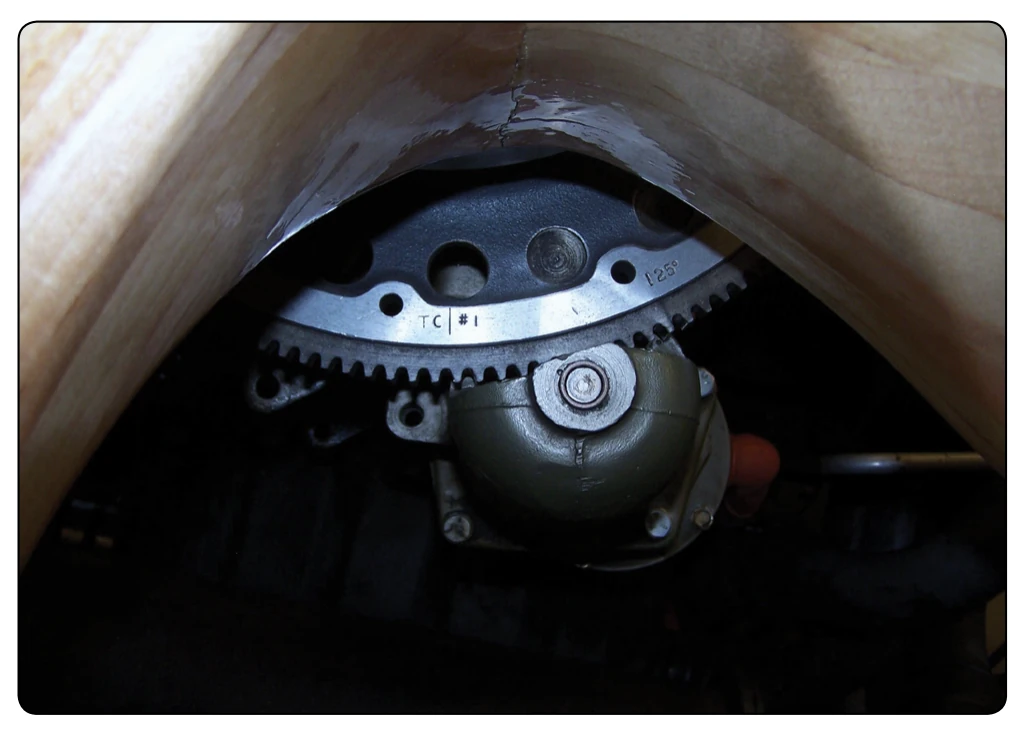
The magneto must be timed by first adjusting or checking the internal timing with the magneto off the engine. This is done by checking and adjusting the ignition points to open at the E-gap position. The chamfered tooth should line up (reference timing mark for the magneto) in the middle of the timing window. The magneto is set to fire the No. 1 cylinder. Remove the most accessible spark plug from the No. 1 cylinder. Pull the propeller through in the direction of rotation until the No. 1 piston is coming up on the compression stroke. This can be determined by holding a thumb over the spark plug hole until the compression air is felt. Set the engine crankshaft at the prescribed number of degrees ahead of true top dead center as specified in the applicable manufacturer’s instruction, usually using the timing marks on the engine. With the engine set at a prescribed number of degrees ahead of true top dead center on the compression stroke and with final movement of the engine stopped in the direction of normal rotation, the magneto can be installed on the engine. [Figure 4-53]
While holding the magneto drive in the firing position for the No. 1 cylinder as indicated by the alignment of the reference marks for the magneto, install the magneto drive into the moving them in the flange slots until the breaker points in the magneto just open. If the slots in the mounting flange of the magneto do not permit sufficient movement to effect breaker point opening for the No. 1 cylinder, move the magneto out of position far enough to permit turning the magneto drive shaft. Then, install the magneto in position again and repeat the previous check for point opening.