Chapter 4
Engine Ignition & Electrical Systems
Install the magneto attaching nuts on the studs and tighten slightly. The nuts must not be tight enough to prevent the movement of the magneto assembly when the magneto mounting flange is tapped with a mallet. Reconnect the timing light to the magneto and breaker points. With the light and ignition switch turned on, rotate the magneto assembly first in the direction of rotation and then in the opposite direction. This is done to determine that the points just opened. After completing this adjustment, tighten the mounting nuts. Move the propeller one blade opposite the direction of rotation and then, while observing the timing light, move the propeller in the direction of rotation until the prescribed number of degrees ahead of top dead center is reached. Be sure that the lights for both sets of points come on points open, within the prescribed timing position.
Both right and left sets of breaker points should open at the same instant, proper magneto-to-engine timing exists, and all phases of magneto operation are synchronized. Some early engines had what was referred to as staggered timing where one magneto would fire at a different number of degrees before top dead center on the compression stroke. In this case, each magneto had to be timed separately. If staggered ignition timing is used, the spark plug nearest the exhaust valve will fire first.
In the following example, a timing light is used for timing the magneto to the engine. The timing light is designed in such a way that one of two lights come on when the points open. The timing light incorporates two lights. When connecting the timing light to the magneto, the leads should be connected so that the light on the right side of the box represents the breaker points on the right magneto, and the light on the left side represents the left magneto breaker points. The black lead or ground lead must be attached to the engine or an effective ground. When using the timing light to check a magneto in a complete ignition system installed on the aircraft, the ignition switch for the engine must be turned to both. Otherwise, the lights do not indicate breaker point opening.
Performing Ignition System Checks
The ignition system has checks performed on it during the aircraft engine run-up, which is the engine check before each flight. The magneto check, as it is usually referred to, is performed during the engine run-up check list.
One other check is accomplished prior to engine shutdown. The ignition system check is used to check the individual magnetos, harnesses, and spark plugs. After reaching the engine rpm specified for the ignition system check, allow the rpm to stabilize. Place the ignition switch in the right position and note the rpm drop on the tachometer. Return the switch to the both position. Allow the switch to remain in the both position for a few seconds so that the rpm stabilizes again. Place the ignition switch in the left position and again note the rpm drop. Return the ignition switch to the both position. Note the amount of total rpm drop that occurs for each magneto position. The magneto drop should be even for both magnetos and is generally in the area of a 25–75 rpm drop for each magneto. Always refer to the aircraft operating manual for specific information. This rpm drop is because operating on one magneto combustion is not as efficient as it is with two magnetos providing sparks in the cylinder.
Remember, this tests not only the magnetos but also the ignition leads and spark plugs. If either magneto has excessive rpm drop while operating by itself, the ignition system needs to be checked for problems. If only one magneto has a high magneto drop, the problem can be isolated and corrected by operating on that magneto. This ignition system check is usually performed at the beginning of the engine run-up because rpm drops not within the prescribed limits affect later checks.
Ignition Switch Check
The ignition switch check is performed to see that all magneto ground leads are electrically grounded. The ignition switch check is usually made at 700 rpm. On those aircraft engine installations that do not idle at this low rpm, set the engine speed to the lowest possible to perform this check. When the speed to perform this check is obtained, momentarily turn the ignition switch to the off position. The engine should completely quit firing. After a drop of 200–300 rpm is observed, return the switch to the both position as rapidly as possible. Do this quickly to eliminate the possibility of afterfire and backfire when the ignition switch is returned to both.
If the ignition switch is not returned quickly enough, the engine rpm drops off completely and the engine stops. In this case, leave the ignition switch in the off position and place the mixture control in the idle-cutoff position to avoid overloading the cylinders and exhaust system with raw fuel. When the engine has completely stopped, allow it to remain inoperative for a short time before restarting.
If the engine does not cease firing in the off position, the magneto ground lead, more commonly referred to as the P lead, is open, and the trouble must be corrected. This means that one or more of the magnetos are not being shut off even when the ignition switch is in the off position. Turning the propeller of this engine can result in personnel injury or death. If the propeller is turned in this condition, the engine can start with personnel in the propeller arch.
Maintenance & Inspection of Ignition Leads
Inspection of ignition leads should include both a visual and an electrical test. During the visual test, the lead cover should be inspected for cracks or other damage, abrasions, mutilated braid, or other physical damage. Inspect leads for overheating if routed close to exhaust stacks. Disconnect the harness coupling nuts from the top of the spark plugs and remove the leads from the spark plug lead well. Inspect the contact springs and compression springs for any damage or distortion and the sleeves for cracks or carbon tracking. The coupling nut that connects to the spark plug should be inspected for damaged threads or other defects.
Each lead should be checked for continuity using a hightension lead tester by connecting the black lead to the contact spring and the red lead to the eyelet of the same lead in the cover. The continuity lamp on the tester should illuminate when tested. The insulation resistance test of each lead is accomplished using the high-tension lead tester by attaching the red, or high-voltage, lead to the spring of the harness lead. Then, attach the black lead to the ferrule of the same lead. Depress the press-to-test push button switch on the lead tester. Observe that the indictor lamp flashes and gap fires simultaneously as long as the press-to-test switch is held in the depressed position.
If the indicator lamp flashes and the gap fails to fire, the lead under test is defective and must be replaced. The indicator lamp flashes to show that a high-voltage impulse was sent out. If it fails to pass through the tester, then the electrical pulse leaked through the wire showing it to be defective.
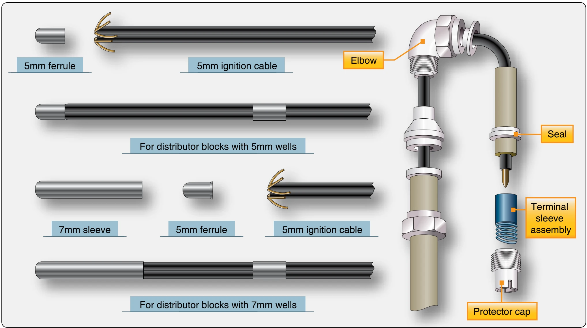
When defective leads are revealed by an ignition harness test, continue the test to determine whether the leads or distributor block are defective. If the difficulty is in an individual ignition lead, determine whether the electrical leak is at the spark plug elbow or elsewhere. Remove the elbow, pull the ignition lead out of the manifold a slight amount, and repeat the harness test on the defective lead. If this stops the leakage, cut away the defective portion of the lead and reinstall the elbow assembly, integral seal, and terminal (sometimes referred to as cigarette). [Figure 4-54] When installing the leads, you should avoid bends because weak points may develop in the insulation through which high-tension current can leak.
If the lead is too short to repair in the manner described, or the electrical leak is inside the harness, replace the defective lead. Single ignition lead replacement procedures are as follows:
- Disassemble the magneto or distributor so that the distributor block is accessible.
- Loosen the piercing screw in the distributor block for the lead to be replaced, and remove the lead from the distributor block.
- Remove approximately 1 inch of insulation from the distributor block end of the defective lead and approximately 1 inch of insulation from the end of the replacement cable. Splice this end to the end of the lead to be replaced and solder the splice.
- Remove the elbow adapter from the spark plug end of the defective lead, then pull the old lead out and put the new lead into the harness. While pulling the leads through the harness, have someone push the replacement lead into the ignition manifold at the distributor end to reduce the force required to pull the lead through the ignition manifold.
- When the replacement lead has been pulled completely through the manifold, force the ignition lead up into the manifold from the distributor block end to provide extra length for future repairs, which may be necessary because of chafing at the spark plug elbow.
- Remove approximately 3⁄8 inch of insulation from the distributor block end. Bend the ends of the wire back and prepare the ends of the cable for installation into the distributor block well. Insert the lead in the distributor and tighten the piercing screw.
- Remove approximately ¼ inch of insulation from the spark plug end of the lead and install the elbow, integral seal, and cigarette. [Figure 4-54]
- Install a marker on the distributor end of the cable to identify its cylinder number. If a new marker is not available, use the marker removed from the defective cable.