
Chapter 4
Engine Ignition & Electrical Systems
Repair
Tighten and secure as required and replace faulty components and wiring. Secure, tighten, and safety as required.
Removal, Maintenance, & Installation of Ignition System Components
The following instructions are typical procedures suggested by many gas turbine manufacturers. These instructions are applicable to the engine ignition components. Always consult the applicable manufacturer’s instructions before performing any ignition system maintenance.
Ignition System Leads
- Remove clamps securing ignition leads to engine.
- Remove safety wire and disconnect electrical connectors from exciter units.
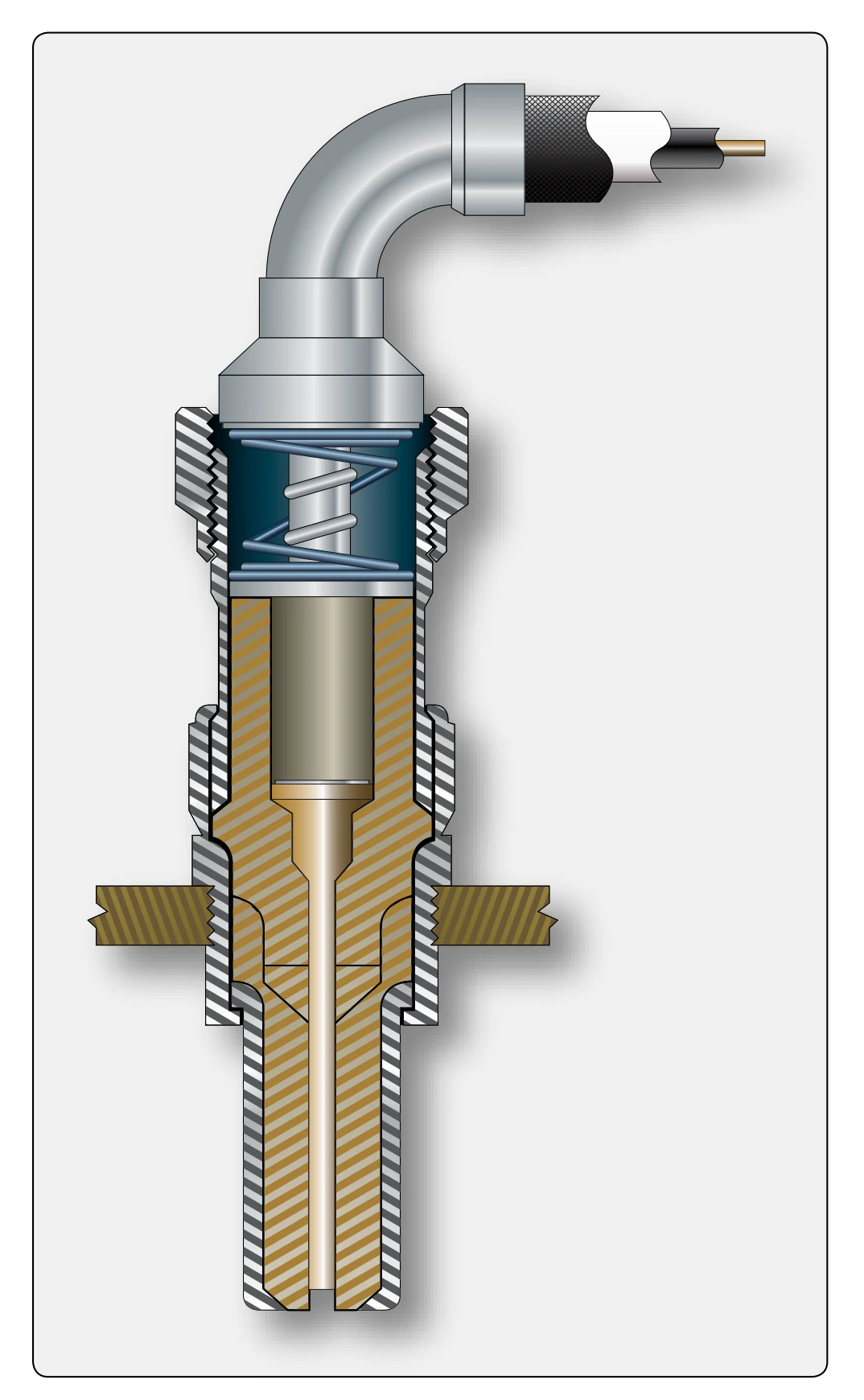
- Remove safety wire and disconnect lead from igniter plug.
- Discharge any electrical charge stored in the system by grounding and remove ignition leads from engine.
- Clean leads with approved dry cleaning solvent.
- Inspect connectors for damaged threads, corrosion, cracked insulators, and bent or broken connector pins.
- Inspect leads for worn or burned areas, deep cuts, fraying, and general deterioration.
- Perform continuity check of ignition leads.
- Reinstall leads, reversing the removal procedure.
Igniter Plugs
- Disconnect ignition leads from igniter plugs. A good procedure to perform before disconnecting the ignition lead is to disconnect the low-voltage primary lead
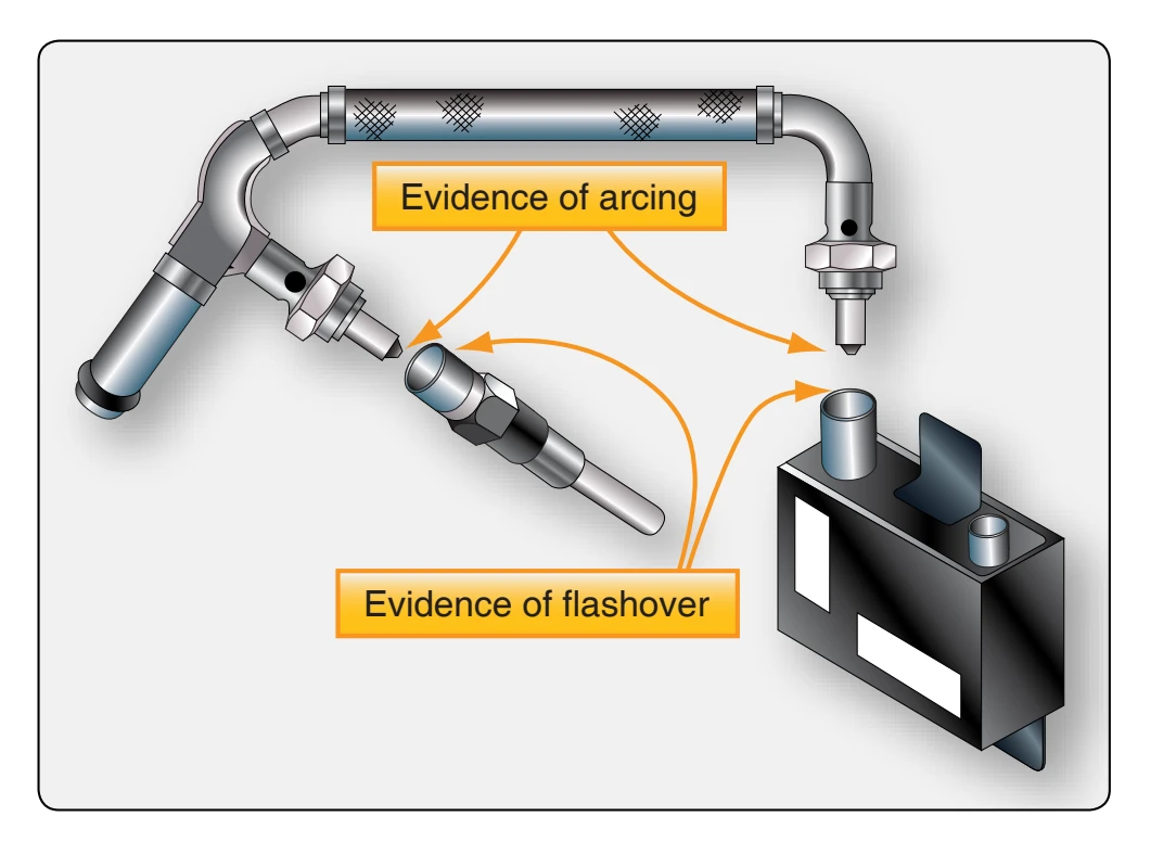
from the ignition exciter unit and wait at least one minute to permit the stored energy to dissipate before disconnecting the high-voltage cable from the igniter.
- Remove igniter plugs from mounts.
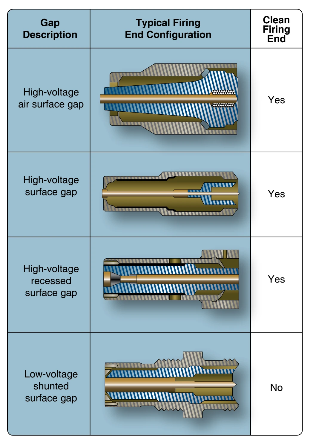
- Inspect igniter plug gap surface material. Before inspection, remove residue from the shell exterior using a dry cloth. Do not remove any deposits or residue from the firing end of the low-voltage igniters. High-voltage igniters can have the firing end cleaned to aid in inspection. [Figure 4-79]
- Inspect for fretting of igniter plug shank.
- Replace an igniter plug whose surface is granular, chipped, or otherwise damaged.
- Replace dirty or carbonized igniter plugs.
- Install igniter plugs in mounting pads.
- Check for proper clearance between chamber liner and igniter plug.
- Tighten igniter plugs to manufacturer’s specified torque.
- Safety wire igniter plugs.
Powerplant Electrical Systems
The satisfactory performance of any modern aircraft depends to a great degree on the continuing reliability of electrical systems and subsystems. Improperly or carelessly installed or maintained wiring can be a source of both immediate and potential danger. The continued proper performance of electrical systems depends upon the knowledge and technique of the mechanic who installs, inspects, and maintains the electrical wire and cable of the electrical systems.
The procedures and practices outlined in this section are general recommendations and are not intended to replace the manufacturer’s instructions in approved practices.
For the purpose of this discussion, a wire is described as a single solid conductor, or a stranded conductor, covered with an insulating material. [Figure 4-80] The term “cable,” as used in aircraft electrical installations, includes the following:
- Multiconductor cable—two or more separately insulated conductors in the same jacket.
- Twisted pair—two or more separately insulated conductors twisted together.
- Shielded cable—one or more insulated conductors, covered with a metallic braided shield.
- Radio frequency cable—a single, insulated center conductor with a metallic braided outer conductor. The concentricity of the center conductor and the outer conductor is carefully controlled during manufacture to ensure that they are coaxial.