
Chapter 4
Engine Ignition & Electrical Systems
All high-voltage in the triggering circuits is completely isolated from the primary circuits. The complete exciter is hermetically sealed, protecting all components from adverse operating conditions, eliminating the possibility of flashover at altitude due to pressure change. This also ensures shielding against leakage of high-frequency voltage interfering with the radio reception of the aircraft.
Capacitor Discharge Exciter Unit
This capacity-type system provides ignition for turbine engines. Like other turbine ignition systems, it is required only for starting the engine; once combustion has begun, the flame is continuous. [Figure 4-74]
The energy is stored in capacitors. Each discharge circuit incorporates two storage capacitors; both are located in the exciter unit. The voltage across these capacitors is stepped up by transformer units. At the instant of igniter plug firing, the resistance of the gap is lowered sufficiently to permit the larger capacitor to discharge across the gap. The discharge of the second capacitor is of low-voltage, but of very high
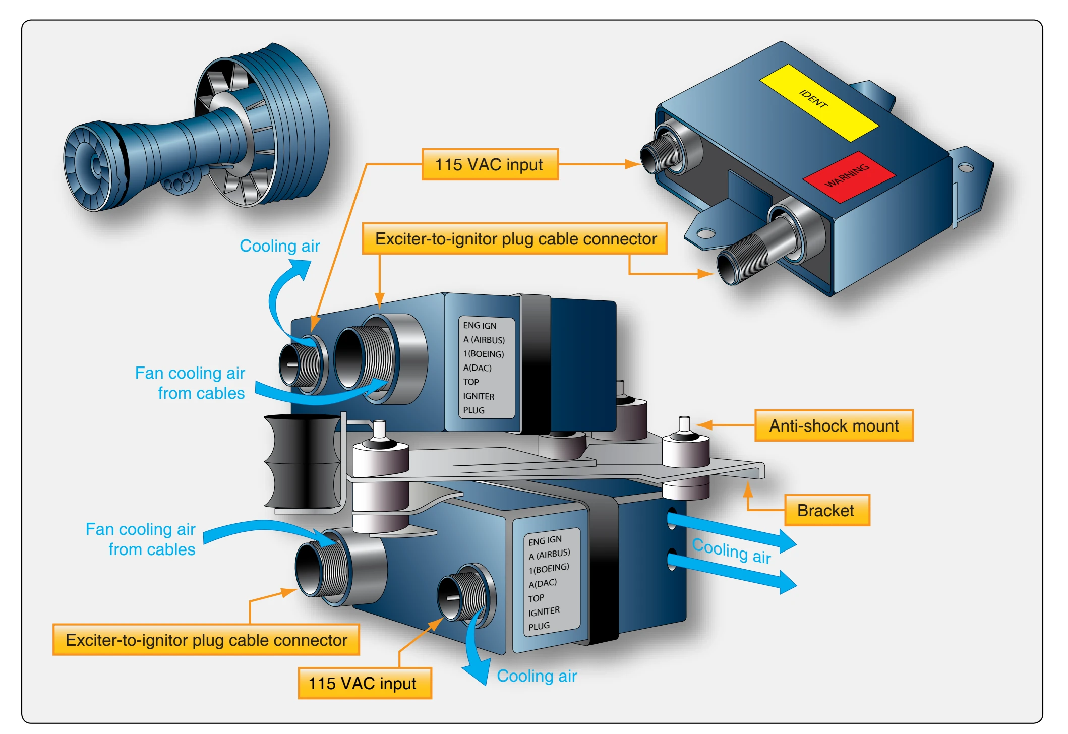
energy. The result is a spark of great heat intensity, capable of not only igniting abnormal fuel mixtures but also burning away any foreign deposits on the plug electrodes.
The exciter is a dual unit that produces sparks at each of the two igniter plugs. A continuous series of sparks is produced until the engine starts. The power is then cut off, and the plugs do not fire while the engine is operating other than on continuous ignition for certain flight conditions. This is why the exciters are air cooled to prevent overheating during long use of continuous ignition.
Igniter Plugs
The igniter plug of a turbine engine ignition system differs considerably from the spark plug of a reciprocating engine ignition system. [Figure 4-75] Its electrode must be capable of withstanding a current of much higher energy than the electrode of a conventional spark plug. This high energy current can quickly cause electrode erosion, but the short periods of operation minimize this aspect of igniter maintenance. The electrode gap of the typical igniter plug is designed much larger than that of a spark plug since the operating pressures are much lower and the spark can arc more easily than in a spark plug. Finally, electrode fouling, common to the spark plug, is minimized by the heat of the high-intensity spark.
Figure 4-76 is a cutaway illustration of a typical annular-gap igniter plug, sometimes referred to as a long reach igniter because it projects slightly into the combustion chamber liner to produce a more effective spark.
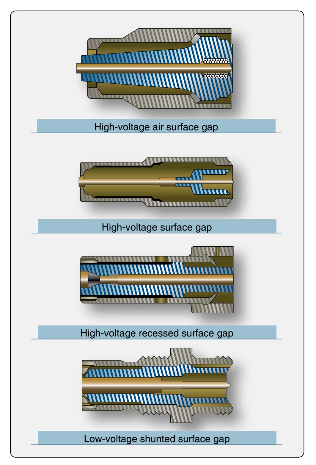
Another type of igniter plug, the constrained-gap plug, is used in some types of turbine engines. [Figure 4-77] It operates at a much cooler temperature because it does not project into the combustion-chamber liner. This is possible because the spark does not remain close to the plug, but arcs beyond the face of the combustion chamber liner.
Turbine Ignition System Inspection & Maintenance
Maintenance of the typical turbine engine ignition system consists primarily of inspection, test, troubleshooting, removal, and installation.
Inspection
Inspection of the ignition system normally includes the following:
- Ignition lead terminal inspection; ceramic terminal should be free of arcing, carbon tracking and cracks.
- The grommet seal should be free of flashover and carbon tracking. [Figure 4-78]
- The wire insulation should remain flexible with no evidence of arcing through the insulation.
- Inspect the complete system for security of component mounting, shorts or high-voltage arcing, and loose connections.
Check System Operation
The igniter can be checked by listening for a snapping noise as the engine begins to turn, driven by the starter. Though the following procedure is not common practice and should only be used when the maintenance manual suggests it as an alternative method, the igniter can also be checked by removing it and activating the start cycle, noting the spark across the igniter.