
Chapter 4
Engine Ignition & Electrical Systems
Figure 4-70 demonstrates four faults that may occur. Fault A shows a short from one cable conductor to another. This fault usually causes misfiring, since the spark is short circuited to a plug in a cylinder where the cylinder pressure is low. Fault B illustrates a cable with a portion of its insulation scuffed away. Although the insulation is not completely broken down, more than normal leakage exists, and the spark plug to which this cable is connected may be lost during takeoff when the manifold pressure is quite high. Fault C is the result of condensation collecting in the lowest portion of the ignition manifold. This condensation may completely evaporate during engine operation, but the carbon track that is formed by the initial flashover remains to allow continued flashover whenever high manifold pressure exists. Fault D may be caused by a flaw in the insulation or the result of a weak spot in the insulation that is aggravated by the presence of moisture. However, since the carbon track is in
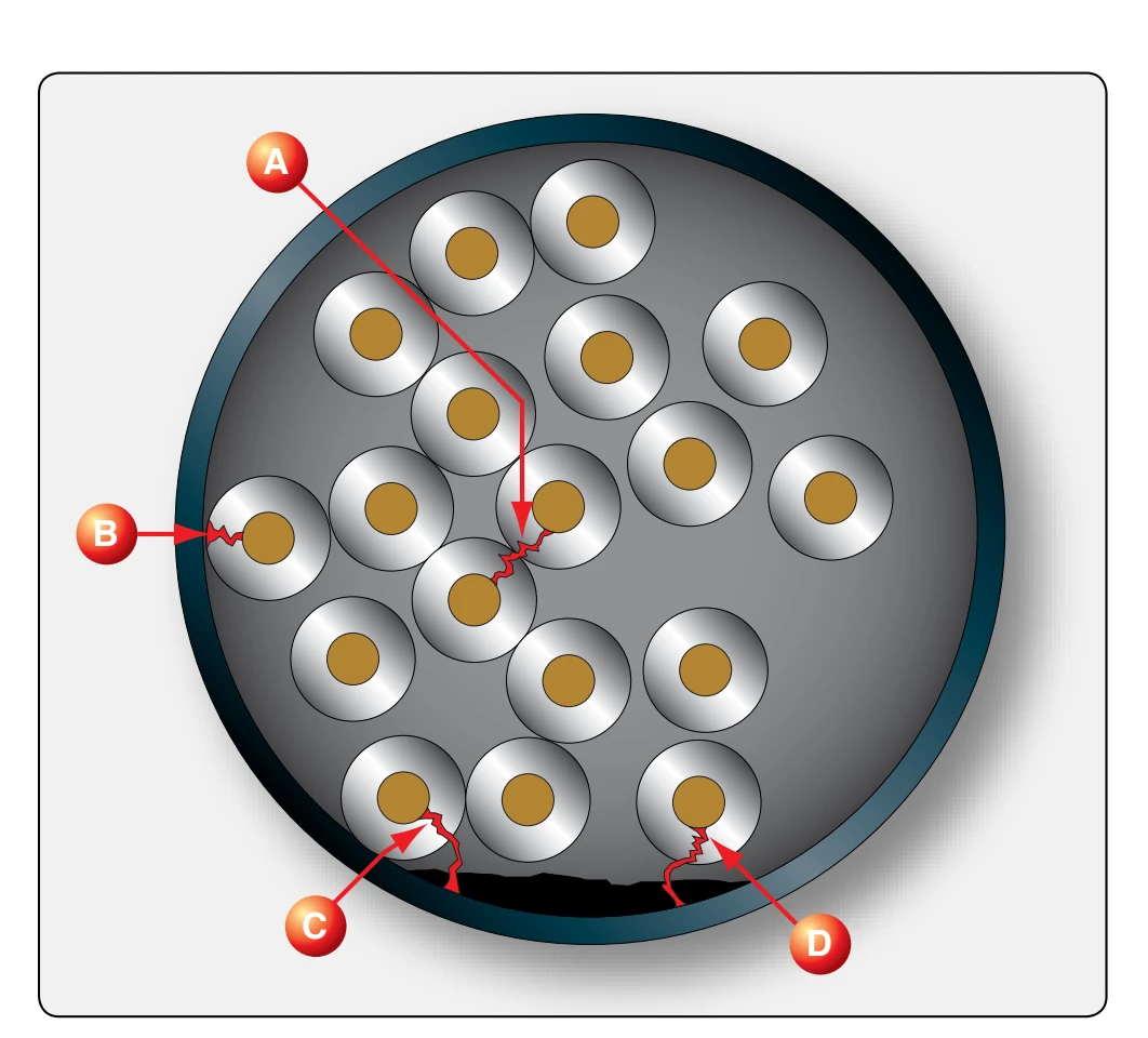
direct contact with the metal shielding, it probably results in flashover under all operating conditions.
Harness Testing
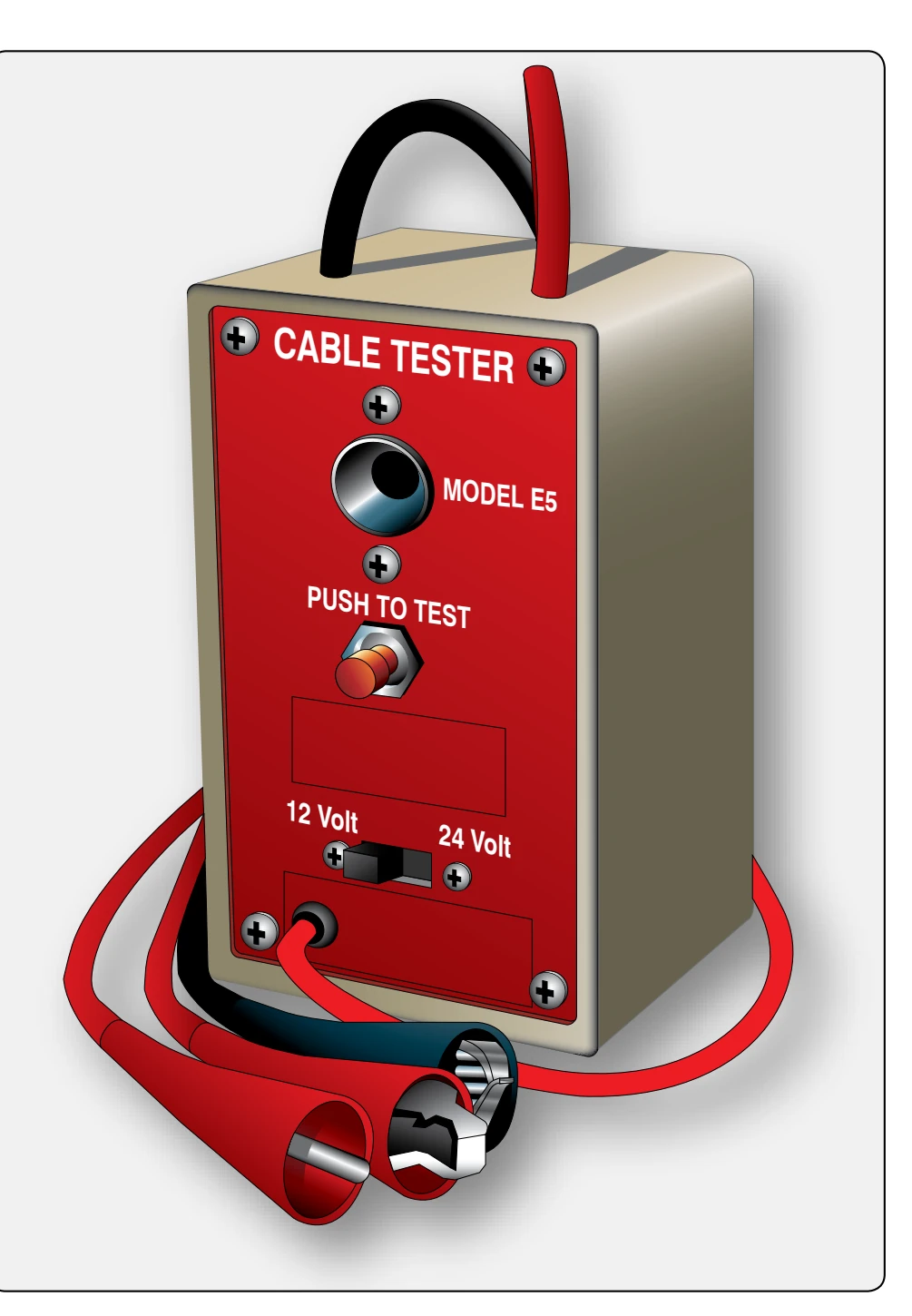
The electrical test of the ignition harness checks the condition or effectiveness of the insulation around each cable in the harness. [Figure 4-71] This test involves application of a definite voltage to each lead, and then measurement with a very sensitive meter of the amount of current leakage between the lead and the grounded harness manifold. This reading, when compared with known specifications, becomes a guide to the condition or serviceability of the cable. As mentioned earlier, there is a gradual deterioration of flexible insulating material. When new, the insulation has a low rate of conductivity; so low that, under several thousand volts of electrical pressure, the current leakage is only a very few millionths of an ampere. Natural aging causes an extremely slow, but certain, change in the resistance of insulating material, allowing an ever-increasing rate of current leakage. The procedures for testing ignition harness and leads were discussed earlier in this chapter.
Turbine Engine Ignition Systems
Since turbine ignition systems are operated mostly for a brief period during the engine-starting cycle, they are, as a rule, more trouble-free than the typical reciprocating engine ignition system. The turbine engine ignition system does not need to be timed to spark during an exact point in the operational cycle. It is used to ignite the fuel in the combustor and then it is switched off. Other modes of turbine ignition system operation, such as continuous ignition that is used at a lower voltage and energy level, are used for certain flight conditions.
Continuous ignition is used in case the engine were to flame out. This ignition could relight the fuel and keep the engine from stopping. Examples of critical flight modes that use continuous ignition are takeoff, landing, and some abnormal and emergency situations.
Most gas turbine engines are equipped with a high-energy, capacitor-type ignition system and are air cooled by fan airflow. Fan air is ducted to the exciter box, and then flows around the igniter lead and surrounds the igniter before flowing back into the nacelle area. Cooling is important when continuous ignition is used for some extended period of time. Gas turbine engines may be equipped with an electronic-type ignition system, which is a variation of the simpler capacitortype system.
The typical turbine engine is equipped with a capacitor-type, or capacitor discharge, ignition system consisting of two identical independent ignition units operating from a common low-voltage (DC) electrical power source: the aircraft battery, 115AC, or its permanent magnet generator. The generator is turned directly by the engine through the accessory gear box and produces power any time the engine is turning. The fuel in turbine engines can be ignited readily in ideal atmospheric conditions, but since they often operate in the low temperatures of high altitudes, it is imperative that the system be capable of supplying a high heat intensity spark. Thus, a high-voltage is supplied to arc across a wide igniter spark gap, providing the ignition system with a high degree of reliability under widely varying conditions of altitude, atmospheric pressure, temperature, fuel vaporization, and input voltage.
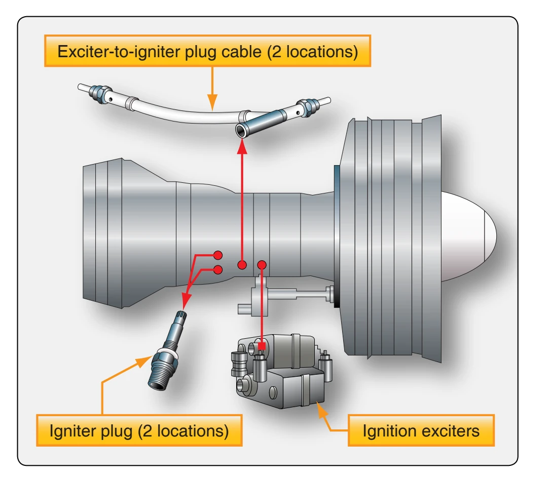
A typical ignition system includes two exciter units, two transformers, two intermediate ignition leads, and two hightension leads. Thus, as a safety factor, the ignition system is actually a dual system designed to fire two igniter plugs. [Figure 4-72]
Figure 4-73 is a functional schematic diagram of a typical older style capacitor-type turbine ignition system. A 24-volt
DC input voltage is supplied to the input receptacle of the exciter unit. Before the electrical energy reaches the exciter unit, it passes through a filter that prevents noise voltage from being induced into the aircraft electrical system. The low-voltage input power operates a DC motor that drives one multilobe cam and one single-lobe cam. At the same time, input power is supplied to a set of breaker points that are actuated by the multilobe cam.
From the breaker points, a rapidly interrupted current is delivered to an auto transformer. When the breaker closes, the flow of current through the primary winding of the transformer establishes a magnetic field. When the breaker opens, the flow of current stops, and the collapse of the field induces a voltage in the secondary of the transformer. This voltage causes a pulse of current to flow into the storage capacitor through the rectifier, which limits the flow to a single direction. With repeated pulses, the storage capacitor assumes a charge, up to a maximum of approximately 4 joules. (Note: 1 joule per second equals 1 watt.) The storage capacitor is connected to the spark igniter through the triggering transformer and a contactor, normally open.
When the charge on the capacitor has built up, the contactor is closed by the mechanical action of the single-lobe cam. A portion of the charge flows through the primary of the triggering transformer and the capacitor connected with it. This current induces a high-voltage in the secondary, which ionizes the gap at the spark igniter.
When the spark igniter is made conductive, the storage capacitor discharges the remainder of its accumulated energy along with the charge from the capacitor in series with the primary of the triggering transformer. The spark rate at the
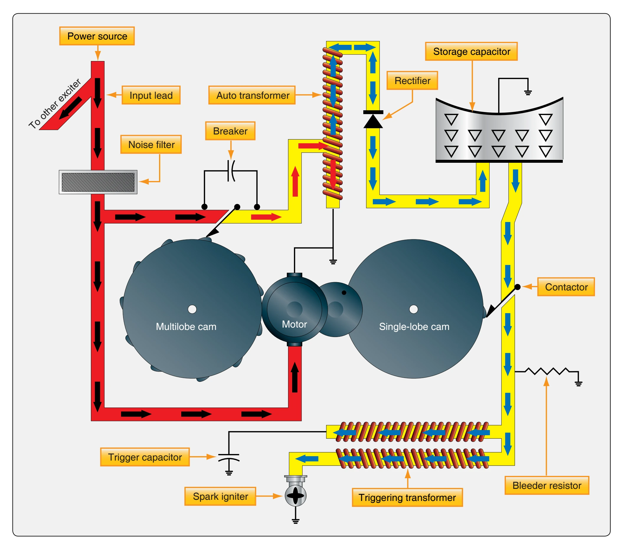
spark igniter varies in proportion to the voltage of the DC power supply that affects the rpm of the motor. However, since both cams are geared to the same shaft, the storage capacitor always accumulates its store of energy from the same number of pulses before discharge. The employment of the high-frequency triggering transformer, with a lowreactance secondary winding, holds the time duration of the discharge to a minimum. This concentration of maximum energy in minimum time achieves an optimum spark for ignition purposes, capable of blasting carbon deposits and vaporizing globules of fuel.