Chapter 4
Engine Ignition & Electrical Systems
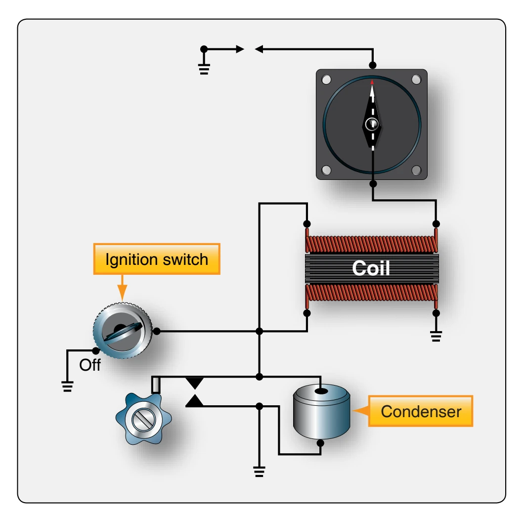
- Through the closed breaker points to ground and
- Through the closed ignition switch to ground.
Figure 4-15 shows that the primary current is not interrupted when the breaker contacts open since there is still a path to ground through the closed, or off, ignition switch. Since primary current is not stopped when the contact points open, there can be no sudden collapse of the primary coil flux field and no high-voltage induced in the secondary coil to fire the spark plug.
As the magnet rotates past the electrical gap (E-gap) position, a gradual breakdown of the primary flux field occurs. But that breakdown occurs so slowly that the induced voltage is too low to fire the spark plug. Thus, when the ignition switch is in the off position with the switch closed, the contact points are as completely short-circuited as if they were removed from the circuit, and the magneto is inoperative.
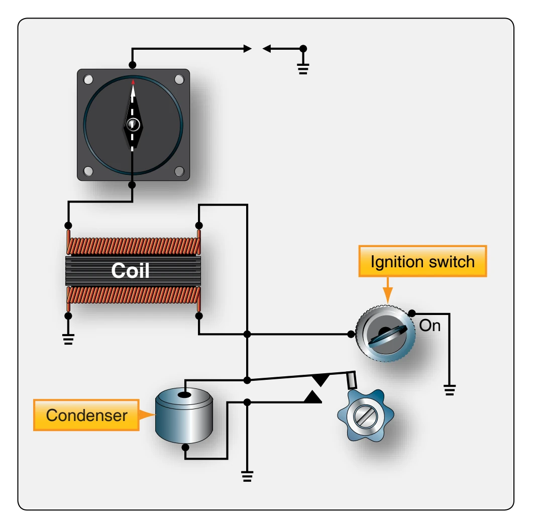
When the ignition switch is placed in the on position, switch open, the interruption of primary current and the rapid collapse of the primary coil flux field is once again controlled or triggered by the opening of the breaker contact points. [Figure 4-16] When the ignition switch is in the on position, the switch has absolutely no effect on the primary circuit.
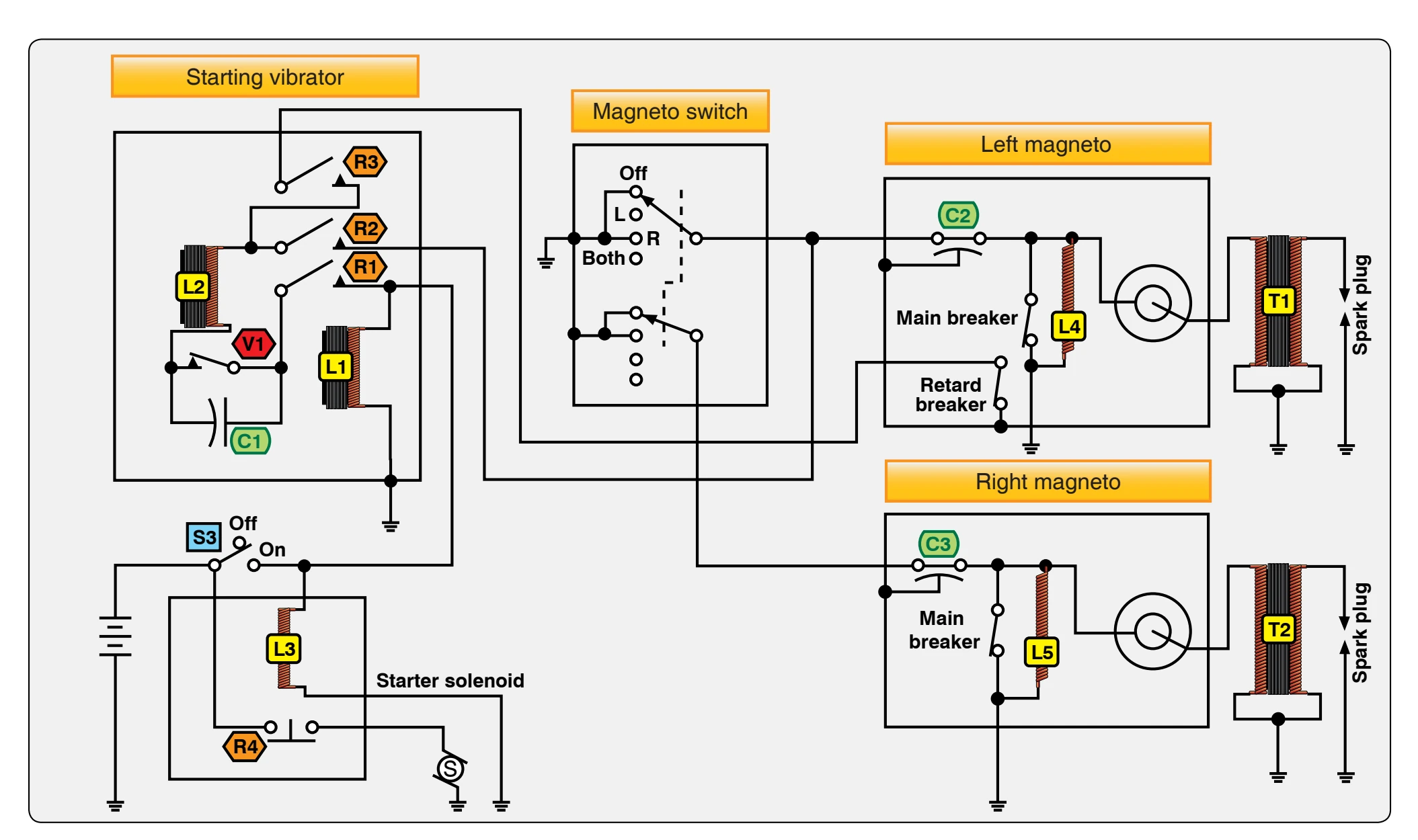
The ignition/starter switch, or magneto switch, controls the magnetos on or off and can also connect the starter solenoid for turning the starter. When a starting vibrator, a box that emits pulsating direct current (DC), is used on the engine, the ignition/starter switch is used to control the vibrator and retard points. This system is explained in detail later in this chapter. Some ignition starter switches have a push to prime feature during the starting cycle. This system allows additional fuel to spray into the intake port of the cylinder during the starting cycle.
Single & Dual High-Tension System Magnetos
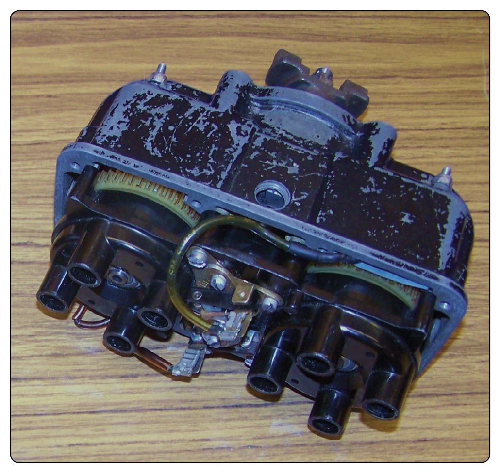
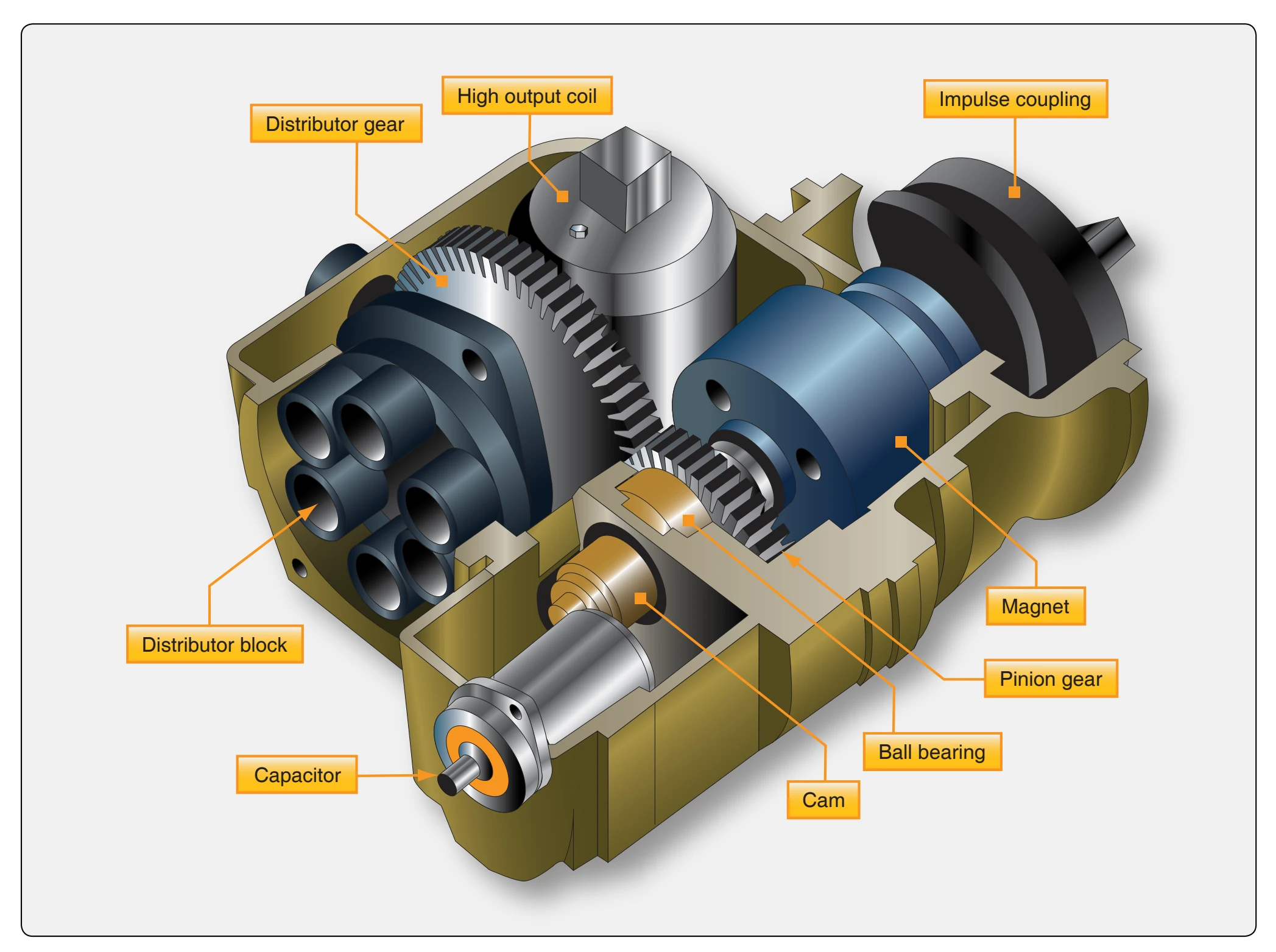
High-tension system magnetos used on aircraft engines are either single or dual type magnetos. The single magneto design incorporates the distributor in the housing with the magneto breaker assembly, rotating magnet, and coil. [Figure 4-17] The dual magneto incorporates two magnetos contained in a single housing. One rotating magnet and a cam are common to two sets of breaker points and coils. Two separate distributor units are mounted in the magneto. [Figure 4-18]
Magneto Mounting Systems
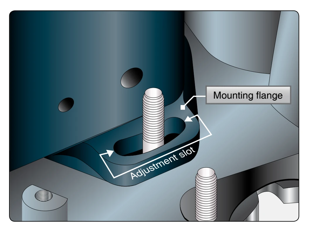
Flange-mounted magnetos are attached to the engine by a flange around the driven end of the rotating shaft of the magneto. [Figure 4-19] Elongated slots in the mounting flange permit adjustment through a limited range to aid in timing the magneto to the engine. Some magnetos mount by the flange and use clamps on each side to secure the magneto to the engine. This design also allows for timing adjustments. Base mounted magnetos are only used on very old or antique aircraft engines.
High- & Low-Tension Magneto Systems
High-tension ignition systems have undergone many refinements and improvements in design. This includes new electronic systems that control more than just providing ignition to the cylinders. High-tension voltage presents certain problems with carrying the high-voltage from the magneto internally and externally to the spark plugs. In early years, it was difficult to provide insulators that could contain the high-voltage, especially at high altitudes when the air pressures were reduced. Another requirement of high-tension systems was that all weather and radio-equipped aircraft have ignition wires enclosed in shielding to prevent radio noise due to high-voltages. Many aircraft were turbosupercharged and operated at increased high altitudes. The low pressure at these altitudes would allow the high-voltage to leak out even more. To meet these problems, low-tension ignition systems were developed.
Electronically, the low-tension system is different from the high-tension system. In the low-tension system, low-voltage is generated in the magneto and flows to the primary winding of a transformer coil located near the spark plug. There, the voltage is increased to high by transformer action and conducted to the spark plug by very short high-tension leads. [Figure 4-20]
The low-tension system virtually eliminates flashover in both the distributor and the harness because the air gaps within the distributor have been eliminated by the use of a brush-type distributor, and high-voltage is present only in short leads between the transformer and spark plug.
Although a certain amount of electrical leakage is characteristic of all ignition systems, it is more pronounced on radioshielded installations because the metal conduit is at ground potential and close to the ignition wires throughout their entire length. In low-tension systems, however, this leakage is reduced considerably because the current throughout most of the system is transmitted at a low-voltage potential. Although