
Chapter 4
Engine Ignition & Electrical Systems
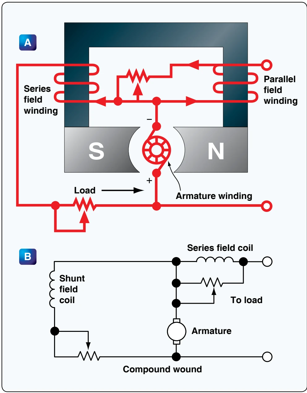
attached to the generator. When replacing a generator, it is important to choose one of the proper ratings.
The rotation of generators is termed either clockwise or counterclockwise, as viewed from the driven end. The direction of rotation may also be stamped on the data plate. It is important that a generator with the correct rotation be used; otherwise, the polarity of the output voltage is reversed. The speed of an aircraft engine varies from idle rpm to takeoff rpm; however, during the major portion of a flight, it is at a constant cruising speed. The generator drive is usually geared to turn the generator between 1 1⁄8 and 1 1⁄2 times the engine crankshaft speed. Most aircraft generators have a speed at which they begin to produce their normal voltage. Called the “coming in” speed, it is usually about 1,500 rpm.
DC Generator Maintenance
The following information about the inspection and maintenance of DC generator systems is general in nature because of the large number of differing aircraft generator systems. These procedures are for familiarization only. Always follow the applicable manufacturer’s instructions for a given generator system. In general, the inspection of the generator installed in the aircraft should include the following items:
- Security of generator mounting.
- Condition of electrical connections.
- Dirt and oil in the generator. If oil is present, check engine oil seals. Blow out any dirt with compressed air.
- Condition of generator brushes.
- Generator operation.
- Voltage regulator operation.
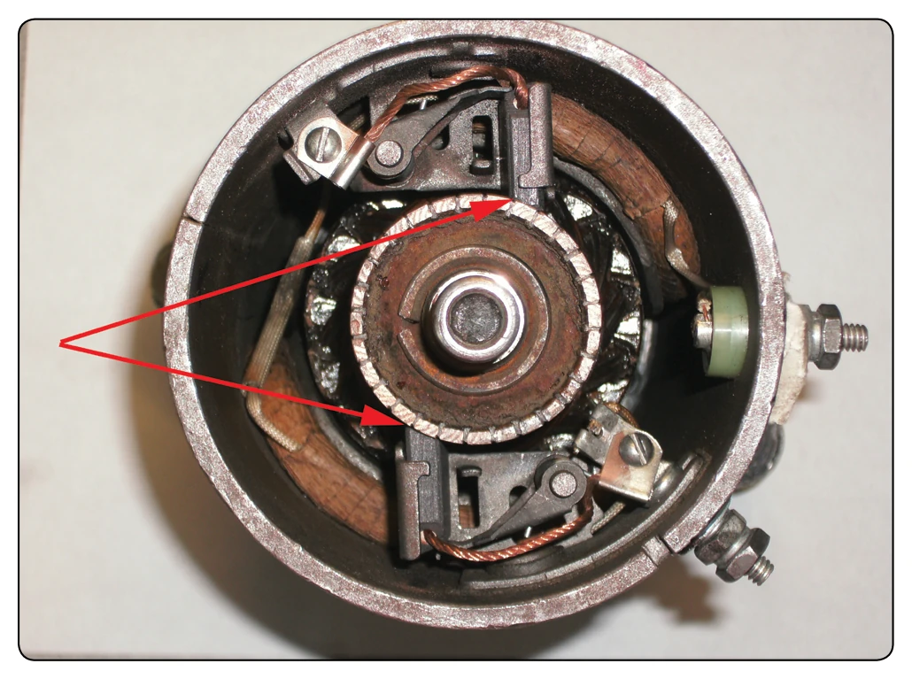
Sparking of brushes quickly reduces the effective brush area in contact with the commutator bars. The degree of such sparking should be determined. Excessive wear warrants a detailed inspection and possible replacement of various components. [Figure 4-24]
Manufacturers usually recommend the following procedures to seat brushes that do not make good contact with slip rings or commutators. Lift the brush sufficiently to permit the insertion of a strip of extra-fine 000 (triple aught) grit, or finer, sandpaper under the brush, rough side towards the carbon brush. [Figure 4-25]
Pull the sandpaper in the direction of armature rotation, being careful to keep the ends of the sandpaper as close to the slip ring or commutator surface as possible in order to avoid rounding the edges of the brush. When pulling the sandpaper back to the starting point, raise the brush so it does not ride
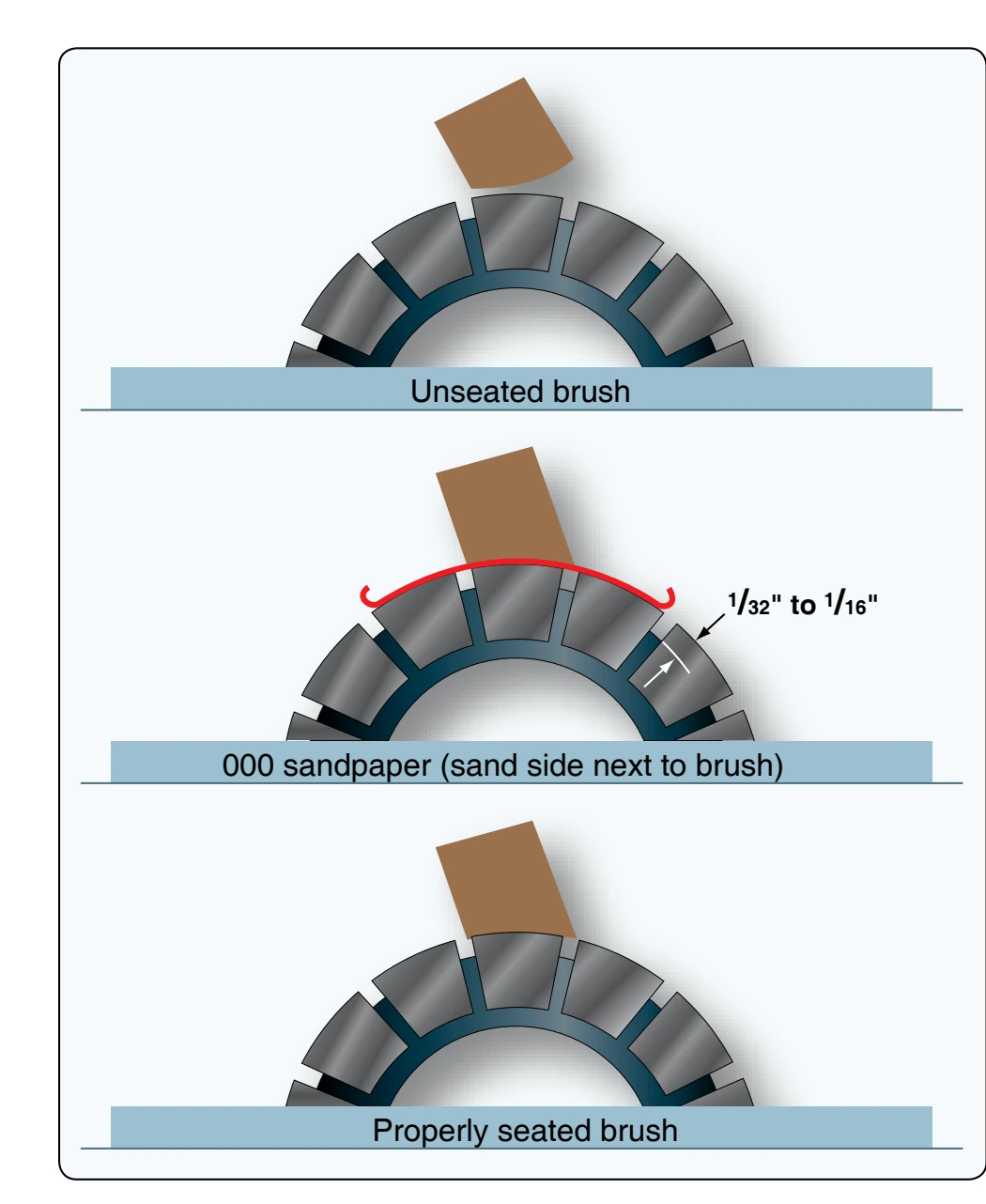
on the sandpaper. Sand the brush only in the direction of rotation. Carbon dust resulting from brush sanding should be thoroughly cleaned from all parts of the generators after a sanding operation.
After the generator has run for a short period, brushes should be inspected to make sure that pieces of sand have not become embedded in the brush. Under no circumstances should emery cloth or similar abrasives be used for seating brushes (or smoothing commutators), since they contain conductive materials that cause arcing between brushes and commutator bars. It is important that the brush spring pressure be correct. Excessive pressure causes rapid wear of brushes. Too little pressure, however, allows bouncing of the brushes, resulting in burned and pitted surfaces. The pressure recommended by the manufacturer should be checked by the use of a spring scale graduated in ounces. Brush spring tension on some generators can be adjusted. A spring scale is used to measure the pressure that a brush exerts on the commutator.
Flexible low-resistance pigtails are provided on most heavy current carrying brushes, and their connections should be securely made and checked at frequent intervals. The pigtails should never be permitted to alter or restrict the free motion of the brush. The purpose of the pigtail is to conduct the current from the armature, through the brushes, to the external circuit of the generator.
FADEC System Description
A FADEC is a solid-state digital electronic ignition and electronic sequential port fuel injection system with only one moving part that consists of the opening and closing of the fuel injector. FADEC continuously monitors and controls ignition, timing, and fuel mixture/delivery/injection, and spark ignition as an integrated control system. FADEC monitors engine operating conditions (crankshaft speed, top dead center position, the induction manifold pressure, and the induction air temperature) and then automatically adjusts the fuel-to-air ratio mixture and ignition timing accordingly for any given power setting to attain optimum engine performance. As a result, engines equipped with FADEC require neither magnetos nor manual mixture control.
This microprocessor-based system controls ignition timing for engine starting and varies timing with respect to engine speed and manifold pressure. [Figure 4-26]
PowerLink provides control in both specified operating conditions and fault conditions. The system is designed to prevent adverse changes in power or thrust. In the event of loss of primary aircraft-supplied power, the engine controls continue to operate using a secondary power source (SPS). As a control device, the system performs self-diagnostics to determine overall system status and conveys this information to the pilot by various indicators on the health status annunciator (HSA) panel. PowerLink is able to withstand storage temperature extremes and operate at the same capacity as a non-FADEC-equipped engine in extreme heat, cold, and high humidity environments.
Low-Voltage Harness
The low-voltage harness connects all essential components of the FADEC System. [Figure 4-26] This harness acts as a signal transfer bus interconnecting the electronic control