
Chapter 7
Propellers
Each constant-speed propeller has an opposing force that operates against the oil pressure from the governor. Flyweights mounted to the blades move the blades in the high pitch direction as the propeller turns. [Figure 7-13] Other forces used to move the blades toward the high pitch direction include air pressure (contained in the front dome), springs, and aerodynamic twisting moment.
Feathering Propellers
Feathering propellers must be used on multi-engine aircraft to reduce propeller drag to a minimum under one or more engine failure conditions. A feathering propeller is a constant-speed propeller used on multi-engine aircraft that has a mechanism to change the pitch to an angle of approximately 90°. A propeller is usually feathered when the engine fails to develop power to turn the propeller. By rotating the propeller blade angle parallel to the line of flight, the drag on the aircraft is greatly reduced. With the blades parallel to the airstream, the propeller stops turning and minimum windmilling, if any, occurs. The blades are held in feather by aerodynamic forces.
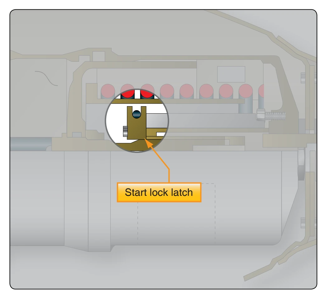
Almost all small feathering propellers use oil pressure to take the propeller to low pitch and blade flyweights, springs, and compressed air to take the blades to high pitch. Since the blades would go to the feather position during shutdown, latches lock the propeller in the low pitch position as the propeller slows down at shutdown. [Figure 7-14] These can be internal or external and are contained within the propeller hub. In flight, the latches are prevented from stopping the blades from feathering because they are held off their seat by centrifugal force. Latches are needed to prevent excess load on the engine at start up. If the blade were in the feathered position during engine start, the engine would be placed under an undue load during a time when the engine is already subject to wear.
Reverse-Pitch Propellers
Additional refinements, such as reverse-pitch propellers (mainly used on turbo props), are included in some propellers to improve their operational characteristics. Almost all reverse-pitch propellers are of the feathering type. A reversepitch propeller is a controllable propeller in which the blade angles can be changed to a negative value during operation.
The purpose of the reversible pitch feature is to produce a negative blade angle that produces thrust opposite the normal forward direction. Normally, when the landing gear is in contact with the runway after landing, the propellers blades can be moved to negative pitch (reversed), which creates thrust opposite of the aircraft direction and slows the aircraft. As the propeller blades move into negative pitch, engine power is applied to increase the negative thrust. This aerodynamically brakes the aircraft and reduces ground roll after landing. Reversing the propellers also reduces aircraft speed quickly on the runway just after touchdown and minimizes aircraft brake wear.
Propeller Governor
A governor is an engine rpm-sensing device and highpressure oil pump. In a constant-speed propeller system, the governor responds to a change in engine rpm by directing oil under pressure to the propeller hydraulic cylinder or by releasing oil from the hydraulic cylinder. The change in oil volume in the hydraulic cylinder changes the blade angle and maintains the propeller system rpm. The governor is set for a specific rpm via the flight deck propeller control, which compresses or releases the governor speeder spring.
A propeller governor is used to sense propeller and engine speed and normally provides oil to the propeller for low pitch position. [Figure 7-15] There are a couple of nonfeathering propellers that operate opposite to this; they are discussed later in this chapter. Fundamental forces, some already discussed, are used to control blade angle variations required for constant-speed propeller operation. These forces are:
- Centrifugal twisting moment—a component of the
centrifugal force acting on a rotating blade that tends at all times to move the blade into low pitch.
- Propeller-governor oil on the propeller piston side— balances the propeller blade flyweights, which moves the blades toward high pitch.
- Propeller blade flyweights—always move the blades toward high pitch.
- Air pressure against the propeller piston—pushes toward high pitch.
- Large springs—push in the direction of high pitch and feather.
- Centrifugal twisting force—moves the blades toward low pitch.
- Aerodynamic twisting force—moves the blades toward high pitch.
All of the forces listed are not equal in strength. The most powerful force is the governor oil pressure acting on the propeller piston. This piston is connected mechanically to the blades; as the piston moves, the blades are rotated in proportion. By removing the oil pressure from the governor, the other forces can force the oil from the piston chamber and move the propeller blades in the other direction.
Governor Mechanism
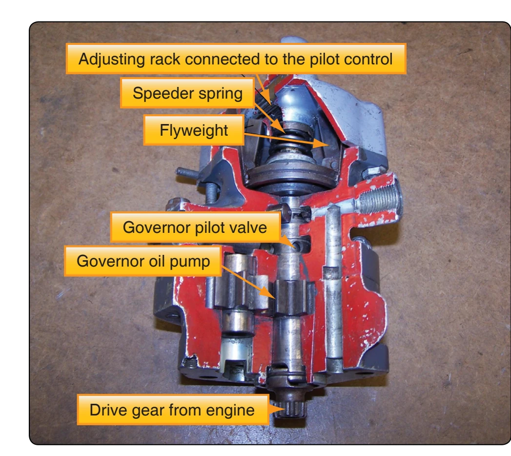
The engine-driven single-acting propeller governor (constant-speed control) receives oil from the lubricating system and boosts its pressure to that required to operate the pitch-changing mechanism. [Figure 7-16] It consists of a gear pump to increase the pressure of the engine oil, a pilot valve controlled by flyweights in the governor to control the flow of oil through the governor to and away from the propeller, and a relief valve system that regulates the operating oil pressures in the governor. A spring called the speeder spring opposes the governor flyweight’s ability to fly outward when turning. The tension on this spring can be adjusted by the propeller control on the control quadrant. The tension of the speeder spring sets the maximum rpm of the engine in the governor mode. As the engine and propeller rpm is increased at the maximum set point (maximum speed) of the governor, the governor flyweights overcome the tension of the speeder spring and move outward. This action moves the pilot valve in the governor to release oil from the propeller piston and allows the blade flyweights to increase blade pitch, which increases the load on the engine, slowing it down or maintaining the set speed.
In addition to boosting the engine oil pressure to produce one of the fundamental control forces, the governor maintains the required balance between control forces by metering to, or draining from, the propeller piston the exact quantity of oil necessary to maintain the proper blade angle for constantspeed operation. The position of the pilot valve, with respect to the propeller-governor metering port, regulates the quantity of oil that flows through this port to or from the propeller.
A speeder spring above the rack opposes the action of the governor flyweights, which sense propeller speed. If the flyweights turn faster than the tension on the speeder spring, they fly out; this is an overspeed condition. To slow the engine propeller combination down, the blade angle (pitch) must be increased. Oil is allowed to flow away from the propeller piston and the flyweights increase the pitch or blade angle slowing the propeller until it reaches an on-speed condition where the force on the governor flyweights and the tension on the speeder spring are balanced. This balance of forces can be disturbed by the aircraft changing attitude (climb or dive) or the pilot changing the tension on the speeder spring with the propeller control on the instrument panel (i.e., if the pilot selects a different rpm).