Chapter 7
Propellers
Underspeed Condition
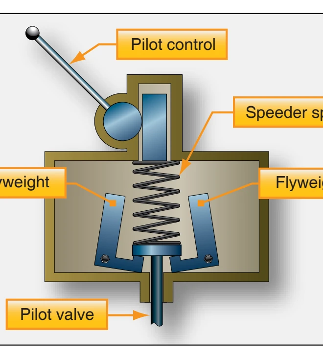
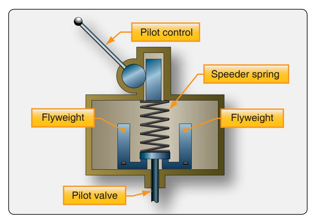
When the engine is operating below the rpm set by the pilot using the flight deck control, the governor is operating in an underspeed condition. [Figure 7-17] In this condition, the flyweights tilt inward because there is not enough centrifugal force on the flyweights to overcome the force of the speeder spring. The pilot valve, forced down by the speeder spring, meters oil flow to decrease propeller pitch and raise engine rpm. If the nose of the aircraft is raised or the blades are moved to a higher blade angle, this increases the load on the engine and the propeller tries to slow down. To maintain a constant speed, the governor senses the decrease in speed and increases
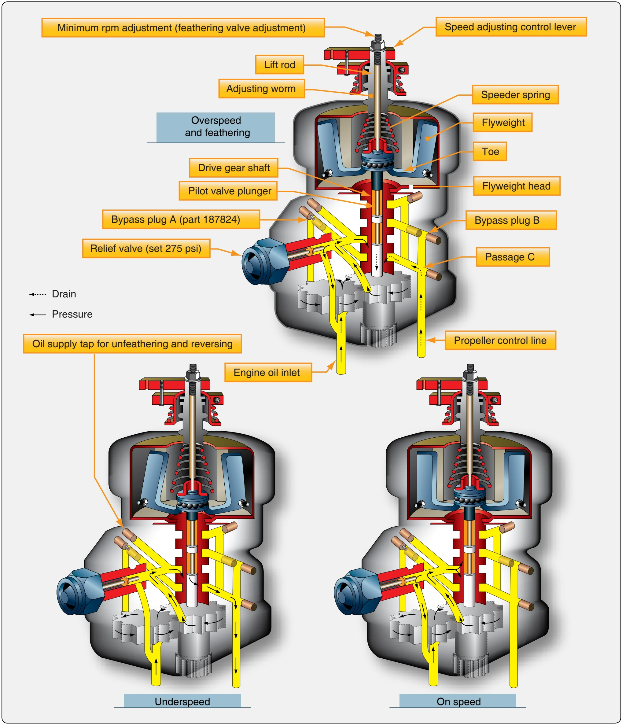
oil flow to the propeller, moving the blades to a lower pitch and allowing them to maintain the same speed. When the engine speed starts to drop below the rpm for which the governor is set, the resulting decrease in centrifugal force exerted by the flyweights permits the speeder spring to lower the pilot valve (flyweights inward), thereby opening the propeller-governor metering port. The oil then flows through the valve port and into the propeller piston causing the blades to move to a lower pitch (a decrease in load).
Overspeed Condition
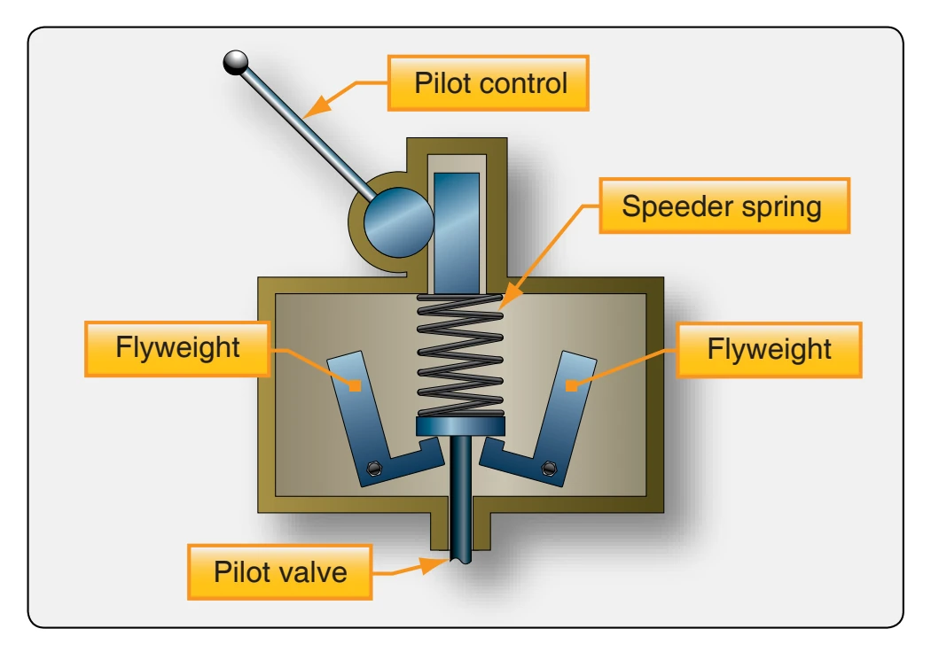
When the engine is operating above the rpm set by the pilot using the flight deck control, the governor is operating in an overspeed condition. [Figure 7-18] In an overspeed condition, the centrifugal force acting on the flyweights is greater than the speeder spring force. The flyweights tilt outward and raise the pilot valve. The pilot valve then meters oil flow to increase propeller pitch and lower engine rpm. When the engine speed increases above the rpm for which the governor is set, note that the flyweights move outward against the force of the speeder spring, raising the pilot valve. This opens the propeller-governor metering port, allowing governor oil flow from the propeller piston allowing flyweights on the blades to increase pitch and slow the engine.
On-Speed Condition
When the engine is operating at the rpm set by the pilot using the flight deck control, the governor is operating on speed. [Figure 7-19] In an on-speed condition, the centrifugal force acting on the flyweights is balanced by the speeder spring, and the pilot valve is neither directing oil to nor from the propeller hydraulic cylinder. In the on-speed condition, the forces of the governor flyweights and the tension on the speeder spring are equal; the propeller blades are not moving or changing pitch. If something happens to unbalance these forces, such as if the aircraft dives or climbs, or the pilot selects a new rpm range through the propeller control (changes tension on the speeder spring), then these forces are unequal and an underspeed or overspeed condition would result. A change in rpm comes about in the governing mode by pilot selection of a new position of the propeller control, which changes the tension of the governor speeder spring or by the aircraft changing attitude. The governor, as a speed-sensing device, causes the propeller to maintain a set rpm regardless of the aircraft attitude. The speeder spring propeller governing range is limited to about 200 rpm. Beyond this rpm, the governor cannot maintain the correct rpm.
Governor System Operation
If the engine speed drops below the rpm for which the governor is set, the rotational force on the engine-driven governor flyweights becomes less. [Figure 7-17] This allows the speeder spring to move the pilot valve downward. With the pilot valve in the downward position, oil from the gear type pump flows through a passage to the propeller and moves the cylinder outward. This in turn decreases the blade angle and permits the engine to return to the on-speed setting. If the engine speed increases above the rpm for which the governor is set, the flyweights move against the force of the speeder spring and raise the pilot valve. This permits the oil in the propeller to drain out through the governor drive shaft. As the oil leaves the propeller, the centrifugal force acting on the flyweights turns the blades to a higher angle, which decreases the engine rpm. When the engine is exactly at the rpm set by the governor, the centrifugal reaction of the flyweights balances the force of the speeder spring, positioning the pilot valve so that oil is neither supplied to nor drained from the propeller. With this condition, propeller blade angle does not change. Note that the rpm setting is made by varying the amount of compression in the speeder spring. Positioning of the speeder rack is the only action controlled manually. All others are controlled automatically within the governor.
Propellers Used on General Aviation Aircraft
An increasing number of light aircraft are designed for operation with governor-regulated, constant-speed propellers. Significant segments of general aviation aircraft are still operated with fixed-pitch propellers. Light-sport aircraft (LSA) use multiblade fixed-pitch composite propellers on up to medium size turbo prop aircraft with reversing propeller systems. Larger transport and cargo turbo prop aircraft use propeller systems with dual or double-acting governors and differential oil pressure to change pitch. Some types of propeller systems are beyond the scope of this text, but several propellers and their systems are described.
Fixed-Pitch Wooden Propellers
Although many of the wood propellers were used on older aircraft, some are still in use. The construction of a fixedpitch, wooden propeller is such that its blade pitch cannot be changed after manufacture. [Figure 7-20] The choice of the blade angle is decided by the normal use of the propeller on an aircraft during level flight when the engine performs at maximum efficiency. The impossibility of changing the blade pitch on the fixed-pitch propeller restricts its use to small aircraft with low horsepower engines in which maximum engine efficiency during all flight conditions is of lesser importance than in larger aircraft. The wooden, fixed-pitch propeller is well suited for such small aircraft because of its light weight, rigidity, economy of production, simplicity of construction, and ease of replacement.
A wooden propeller is not constructed from a solid block but is built up of a number of separate layers of carefully selected and well-seasoned hardwoods. Many woods, such as mahogany, cherry, black walnut, and oak, are used to some extent, but birch is the most widely used. Five to nine separate layers are used, each about 3⁄ inch thick. The several 4 layers are glued together with a waterproof, resinous glue and allowed to set. The blank is then roughed to the approximate shape and size of the finished product. The roughed-out propeller is then allowed to dry for approximately one week to permit the moisture content of the layers to become equalized. This additional period of seasoning prevents warping and cracking that might occur if the blank were immediately carved. Following this period, the propeller is carefully constructed. Templates and bench protractors are used to assure the proper contour and blade angle at all stations.
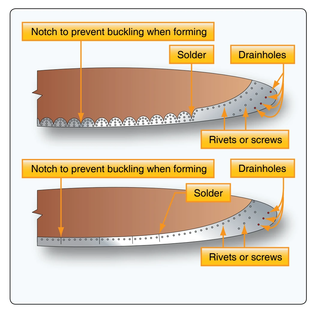
After the propeller blades are finished, a fabric covering is cemented to the outer 12 or 15 inches of each finished blade. A metal tipping is fastened to most of the leading edge and tip of each blade to protect the propeller from damage caused by flying particles in the air during landing, taxiing, or takeoff. [Figure 7-21] Metal tipping may be of terneplate, Monel metal, or brass. Stainless steel has been used to some extent. It is secured to the leading edge of the blade by countersunk wood screws and rivets. The heads of the screws are soldered to the tipping to prevent loosening, and the solder is filed