
Chapter 8
Engine Removal & Replacement
To prevent failure of the engine bearings during the initial start, the engine should be pre-oiled. When an engine has been idle for an extended period of time, its internal bearing surfaces are likely to become dry at points where the corrosion-preventive mixture has dried out or drained away from the bearings. Hence, it is necessary to force oil throughout the entire engine oil system. If the bearings are dry when the engine is started, the friction at high rpm destroys the bearings before lubricating oil from the engine-driven oil pump can reach them.
There are several methods of pre-oiling an engine. The method selected should provide an expeditious and adequate pre-oiling service. Before using any pre-oiling method, remove one spark plug from each cylinder to allow the engine to be turned over more easily with the starter. Also, connect an external source of electrical power (auxiliary power unit) to the aircraft electrical system to prevent an excessive drain on the aircraft battery.
In using some types of pre-oilers, such as that shown in Figure 8-12, the oil line from the inlet side of the enginedriven oil pump must be disconnected to permit the pre-oiler tank to be connected at this point. Then, a line must be disconnected, or an opening made in the oil system at the nose of the engine, to allow oil to flow out of the engine. Oil flowing out of the engine indicates the completion of the pre-oiling operation, since the oil has now passed through the entire system.
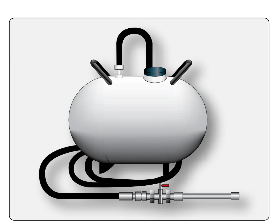
In order to force oil from the pre-oiler tank through the engine, apply air pressure to the oil in the tank while the engine is being turned through with the starter. When this action has forced oil through the disconnection at the nose of the engine, stop cranking the engine and disconnect the pre-oiler tank. A motor-driven oil pump can also be used to pump oil through the engine during the pre-oiling operation.
When no external means of pre-oiling an engine are available, the engine oil pump may be used. Fill the engine oil tank, or crankcase, to the proper level. Then, with the mixture in the idle cutoff position (reciprocating engine), the fuel shutoff valve and ignition switches in the off position, and the throttles fully open, crank the engine with the starter until the oil pressure gauge mounted on the instrument panel indicates oil pressure.
After the engine has been pre-oiled, replace the spark plugs and connect the oil system. Generally, the engine should be operated within 4 hours of being pre-oiled; otherwise, the pre-oiling procedure normally must be repeated.
Fuel System Bleeding
To purge the fuel system of air locks, and to aid in flushing any traces of preservative oil from a pressure carburetor, fuel injector unit, or fuel control (turbine), remove the drain plug in the fuel unit chamber that is farthest from the fuel inlet to the fuel unit. In its place, screw a threaded fitting to a length of hose leading to a suitable container. Then, set the fuel control unit to flow fuel so that fuel is permitted to flow through the system. After ensuring the fuel shutoff and main fuel tank valves are open, turn on the fuel boost pump until there are no traces of preservative oil in the fuel being pumped through the system. The passage of air is indicated by the absence of air mixed in the fuel emerging from the end of the hose submerged in the container of fuel. Air trapped in the system should not be confused with the numerous small air bubbles that may appear as a result of the velocity of the fuel being ejected from the engine’s fuel unit. Usually, after approximately a gallon of fuel has been bled off, the system can be considered safe for operation. After completing the bleeding operation, return all switches and controls to their normal, or off, position, and replace and safety all fuel unit connections disturbed.
Propeller Check
The propeller, if equipped, must be checked before, during, and after the engine has been ground operated. The propeller should be checked for proper torque on the mounting bolts, leaks, vibration, and for correct safety.
A propeller whose pitch-changing mechanism is electrically actuated may be checked before the engine is operated. Propellers whose pitch-changing mechanisms are oil actuated must be checked during engine operation after the normal operating oil temperature has been reached. In addition to checking the increase or decrease in rpm, the feathering cycle of the propeller should also be checked.
Checks & Adjustments After Engine Runup & Operation
After the engine has been ground operated, and again after flight test, operational factors must be adjusted, as necessary, and the entire installation given a thorough visual inspection. These adjustments often include fuel pressure and oil pressure, as well as rechecks of such factors as ignition timing, valve clearances, and idle speed and mixture. If these rechecks are indicated by the manner in which the engine performs.
After both the initial ground runup and the test flight, remove the oil sump plugs and screens and inspect for metal particles. Clean the screens before reinstalling them.
Check all lines for leakage and security of attachment. Especially, check the oil system hose clamps for security as evidenced by oil leakage at the hose connections. Also, inspect the cylinder holddown nuts or cap screws for security and safety. This check should also be performed after the flight immediately succeeding the test flight.
Rigging, Inspections, & Adjustments
The following instructions cover some of the basic inspections and procedures for rigging and adjusting fuel controls, fuel selectors, and fuel shutoff valves.
- Inspect all bellcranks for looseness, cracks, or corrosion.
- Inspect rod ends for damaged threads and the number of threads remaining after final adjustment.
- Inspect cable drums for wear and cableguards for proper position and tension.
While rigging the fuel selector, power controls, and shutoff valve linkages, follow the manufacturer’s step-by-step procedure for the particular aircraft model being rigged. The cables should be rigged with the proper tension with the rigging pins installed. The pins should be free to be removed without any binding; if they are hard to remove, the cables are not rigged properly and should be rechecked. The power lever should have the proper cushion at the idle and full-power positions. The pointers, or indicators, on the fuel control should be within limits. The fuel selectors must be rigged so that they have the proper travel and do not restrict the fuel flow to the engines.