
Chapter 8
Engine Removal & Replacement
The exhaust system should also be carefully connected to prevent the escape of hot gases into the nacelle. When assembling the exhaust system, check all clamps, nuts, and bolts, and replace any in doubtful condition. During assembly, the nuts should be gradually and progressively tightened to the correct torque. The clamps should be tapped with a rawhide mallet as they are being tightened to prevent binding at any point. On some systems, a ball joint connects the stationary portion of the exhaust system to the portion that is attached to the engine. This ball joint absorbs the normal engine movement caused by the unbalanced forces of the engine operation. Ball joints must be installed with the specified clearance to prevent binding when expanded by hot exhaust gases.
Hoses used inside low-pressure systems are generally fastened into place with clamps. Before using a hose clamp, inspect it for security of welding or riveting and for smooth operation of the adjusting screw. A clamp that is badly distorted or materially defective should be rejected. Material defects include extremely brittle or soft areas that may easily break or stretch when the clamp is tightened. After a hose is installed in a system, it should be supported with rubber-lined supporting clamps at regular intervals.
Before installing metal tubing with threaded fittings, ensure the threads are clean and in good condition. Apply sealing compound, of the correct specification for the system, to the threads of the fittings before installing them. While connecting metal tubing, follow the same careful procedure for connecting hose fittings to prevent cross-threading and to ensure correct torque.
When connecting the starter, generator, or various other electrical units within the nacelle, make sure that all lead connections are clean and properly secured. On leads that are fastened to a threaded terminal with a nut, a lock washer is usually inserted under the nut to prevent the lead from working loose. When required, connector plugs can be safetied with steel wire to hold the knurled nut in the fulltight position.
Electrical leads within the engine nacelle are usually passed through either flexible or rigid conduit. The conduit must be anchored, as necessary, to provide a secure installation and bonded when required.
All engine controls must be accurately adjusted to ensure instantaneous response to the control setting. For flexibility, the engine controls are usually a combination of rods and cables. Since these controls are tailored to the model of aircraft in which they are installed, their adjustment must follow exactly the step-by-step procedure outlined in the manufacturer’s instructions for each particular model of aircraft.
Figure 8-11 illustrates a simplified schematic drawing of a throttle control system for a reciprocating aircraft engine. Follow a general procedure for adjusting throttle controls. First, loosen the serrated throttle control arm at the carburetor and back off the throttle stop until the throttle valve is in the fully closed position. After locking the cable drum into position with the locking pin, adjust the control rod to a specified length. Then, attach one end of the control rod to the locked cable drum, and reinstall the throttle control arm on the carburetor in the serrations that allow the other end of the control rod to be attached to it. This correctly connects the control arm to the cable drum.
Now, loosen the cable turnbuckles until the throttle control can be locked at the quadrant with the locking pin. Then, with both locking pins in place, adjust the cables to the correct tension as measured with a tensiometer. Remove the locking pins from the cable drum and quadrant.
Next, adjust the throttle control so that it has a slight cushion action at two positions on the throttle quadrant: one when the carburetor throttle valve is in the full-open position and the other when it is closed to the idle position (stop to stop).
Adjust the cushion by turning the cable turnbuckles equally in opposite directions until the throttle control cushion is correct at the full-open position of the throttle valve. Then, when the throttle arm stop is adjusted to the correct idle speed
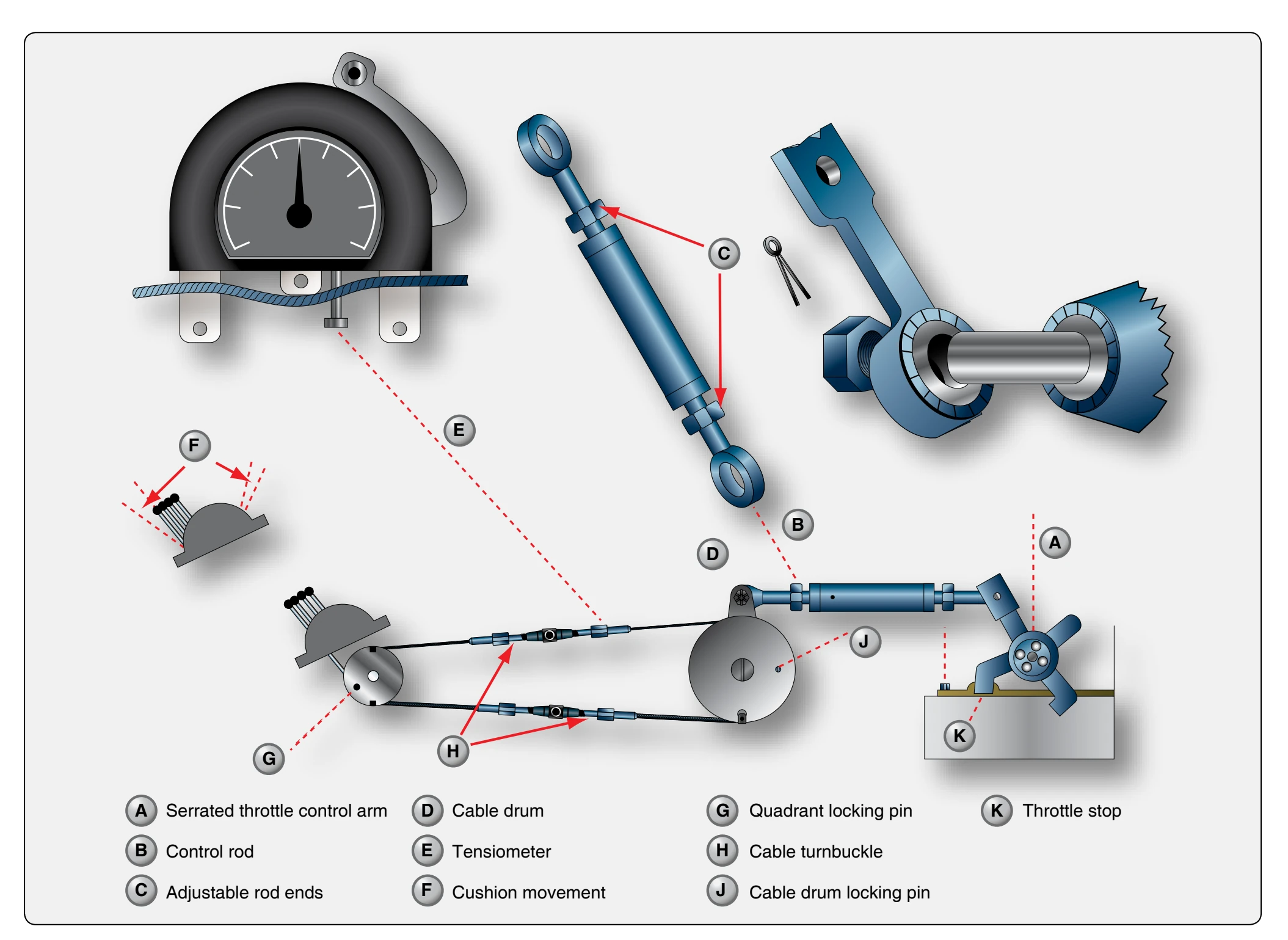
setting, the amount of cushion should be within tolerance at the idle speed position of the throttle valve. The presence of this cushion ensures that the travel of the throttle valve is not limited by the stops on the throttle control quadrant, but that they are opening fully and closing to the correct idle speed as determined by the throttle arm stop.
Adjustment of the engine controls is basically the same on all aircraft regarding the linkage adjustment to a predetermined length for a specific setting of the unit to be controlled. Then adjust cables, if used in the control system, to a specific tension with the control system locked. Finally, the full travel of the unit to be controlled is ensured by establishing the correct cushion in the controls. In general, the same basic procedure is used to connect the linkage of the remaining engine controls. After rigging the engine controls, safety the turnbuckles and castle nuts, and make certain the jam nuts on all control rods are tightened.
On multiengine aircraft, the amount of cushion of all engine controls on each quadrant must be equal so that all are aligned at any specific setting chosen. This eliminates the necessity of setting each control individually to synchronize engine operations.
After the engine has been installed, it is necessary to adjust the cowl flaps, if installed, so that the passage of the cooling air over the engine can be regulated accurately. Operate the system and recheck for opening and closing to the specified limits. Also, check the cowl flap position indicators, if installed, to ensure that they indicate the true position of the cowl flaps. Cowl flaps are doors at the bottom of the rear cowling that are used to control air flow through the cowling.
The oil cooler doors are adjusted in a manner similar to that used to adjust the cowl flaps. In some cases, the procedure is reversed in so far as the door is first adjusted to retract to a specified point, and the limit switch on the motor is set to cut out at this point. Then, the jackscrew is adjusted to permit the door to open only a specified distance, and the open limit switch is set to stop the motor when this point is reached.
After the engine has been completely installed and connected, install the propeller on the aircraft. Before doing so, the thrust bearing retaining nut should be checked for correct torque. If required, the propeller shaft must be coated with light engine oil before the propeller is installed; the propeller governor and anti-icing system must be connected according to applicable manufacturer’s instructions.
Preparation of Engine for Ground & Flight Testing
Pre-Oiling
Before the new engine is flight tested, it must undergo a thorough ground check. Before this ground check can be made, several operations are usually performed on the engine.