
Chapter 8
Engine Removal & Replacement
a hoisting sling. The location of these attaching points varies according to the size and weight distribution of the engine. Figure 8-9 shows a sling supporting an engine that has two attaching points. As a matter of safety, carefully inspect the sling for condition before installing it on the engine.
Before attaching the sling to the hoist, be sure that the hoist has sufficient capacity to lift the engine safely. The engine’s center of gravity (CG) should also be taken into account as the engine is hoisted. A manually operated hoist mounted in a
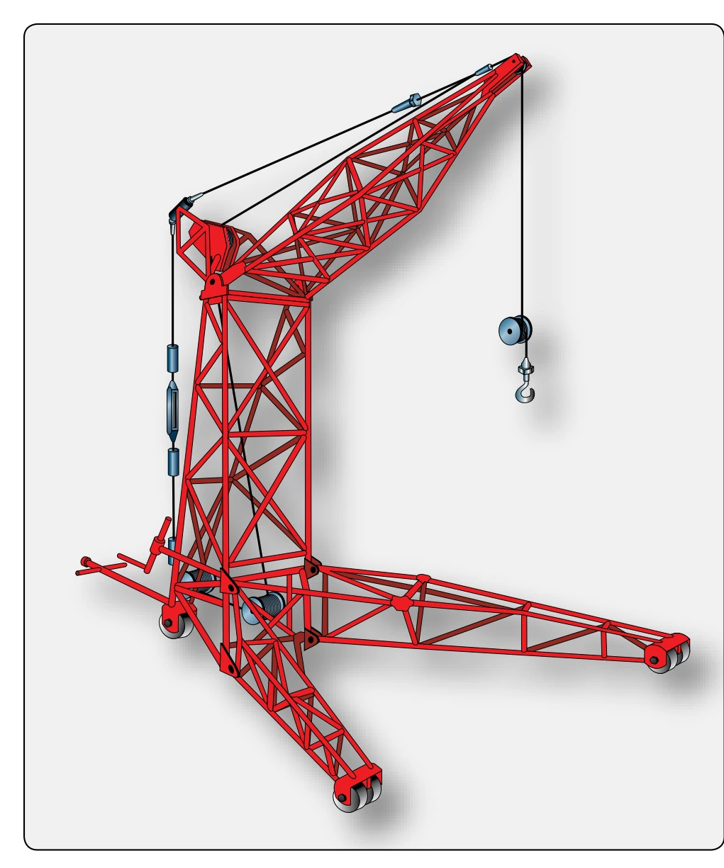
portable frame is shown in Figure 8-10. This hoist assembly is specifically manufactured for the purpose of removing engines and other large assemblies from aircraft. Some frames are fitted with power-operated hoists. These should be used with care, since considerable damage can be done if an inexperienced operator allows a power-operated hoist to overrun. The hoist and frame should also be checked for condition before being used to lift the engine.
Hoisting the Engine
Before the hoist is hooked onto the engine sling, recheck the aircraft tail supports and the wheel chocks. Fasten lines to the engine, at points on the sides or rear, so that the engine can be controlled as it is being hoisted. Hook the hoist onto the sling and hoist the engine just enough to relieve the engine weight from the mount attachments. Remove the nuts from the mount attachments in the order recommended in the manufacturer’s instructions for the aircraft. As the last nuts are being removed, pull back on the lines fastened to the engine (or force it back by other means if lines are not being used), thus steadying the engine. If bolts must be removed from the mount attachments, be sure the engine is under control before doing so. If the bolts are to remain in the mount attachments, the hoist can be gently maneuvered upward or downward as necessary after all the nuts have been removed. Meanwhile, gently relax the backward force on the engine just enough to allow the engine gradual forward movement when it is free from the mount attachments. When the hoist has removed all engine weight from the mount attachments, the engine should be eased gently forward, away from the aircraft. If the engine binds at any point, maneuver it with the hoist until it slips free.
The procedure just discussed applies to removal of most reciprocating and turbine aircraft engines. Any variation in details is outlined in the manufacturer’s instructions. Before attempting any engine removal, always consult these instructions for the aircraft concerned. When the engine has been removed, it can be carefully lowered onto a stand. The engine should be fastened to the stand and prepared for the removal of accessories.
Hoisting & Mounting the Engine for Installation
When the new or overhauled engine is ready to be hoisted for installation, move the engine stand as close as possible to the nacelle in which the replacement is to be installed. Then, attach the sling to the engine and hook the hoist to the sling. Take up the slack until the hoist is supporting most of the engine weight. Next, remove the engine attaching bolts from the stand and hoist the engine clear.
The engine stand may be moved and the hoist frame positioned so the engine can be hoisted easily into the nacelle.
To prevent injury to the crew or damage to the aircraft or engine, be sure that the engine is steadied when moving the hoist frame.
Engine nacelles are rarely designed for the engine to be fitted and bolted into place as though it were being mounted on a bare wall. The engine must be guided into position and mated with its various connections, such as the mounting bolt holes and the exhaust tailpipe. This must be done despite such obstacles as the nacelle framework, ducts, or firewall connections and without leaving a trail of broken and bent parts, scratched paint, or crushed fingers.
When the engine has been aligned correctly in the nacelle, insert the mounting bolts into their holes and start all of the nuts on them. Always use the type of bolt and nut recommended by the manufacturer. Never use an unauthorized substitution of a different type or specification of nut and bolt than that prescribed.
The nuts on the engine mount bolts must be tightened to the torque recommended by the aircraft manufacturer. While the nuts are being tightened, the hoist should support the engine weight sufficiently to allow alignment of the mounting bolts. If the engine is permitted to exert upward or downward pressure on the bolts, it is necessary for the nuts to pull the engine into proper alignment. This results in nuts being tightened to the proper torque value without actually holding the engine securely to the aircraft.
The applicable manufacturer’s instructions outline the sequence for tightening the mounting bolts to ensure security of fastening. After the nuts are safetied and the engine sling and hoist are removed, bonding strips should be connected across each engine mount to provide an electrical path from the mount to the airframe.
Mounting the engine in the nacelle is, of course, only the beginning. All the ducts, electrical leads, controls, tubes, and conduits must be connected before the engine can be operated.
Connections & Adjustments
There are no hard-and-fast rules that direct the order in which units or systems should be connected to the engine. Each maintenance organization normally supplies a worksheet or checklist to be followed during this procedure. This list is based upon past engine installations on each particular aircraft. If this is followed carefully, it serves as a guide for an efficient installation. The following instructions are not a sequence of procedures but a discussion of correct methods for completing an engine installation.
The system of ducts for routing air to the engine varies with all types of aircraft. In connecting them, the goal is to fit the ducts closely at all points of disconnect so that the air they route does not escape its intended path. The duct systems of some aircraft must be pressure checked for leaks. This is done by blocking the system at one end, supplying compressed air at a specified pressure at the other end, and then checking the rate of leakage.
The filters in the air induction system must be cleaned to ensure an unrestricted flow of clean air to the engine and its units. Because methods for cleaning air filters vary with the materials used in the filtering element, clean them in accordance with the technical instructions for the aircraft being serviced.