Chapter 8
Engine Removal & Replacement
A typical plug fitting assembly is shown in Figure 8-5. It also shows a typical junction box assembly, which is used as a disconnect on some aircraft engine installations. After the safety wire is broken, remove all of it from the sleeve nuts that hold the conduit to the junction boxes, as well as from the nuts on the connectors. Wrap moisture proof tape over the exposed ends of connectors to protect them from dirt and moisture. Also, do not leave long electrical cables or conduits hanging loose, since they may become entangled with some part of the aircraft while the engine is being hoisted. It is a good practice to coil all lengths of cable or flexible conduit neatly, and tie
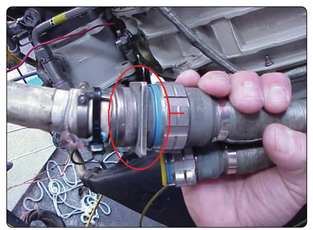
or tape them to some portion of the assembly being removed.
Disconnection of Engine Controls
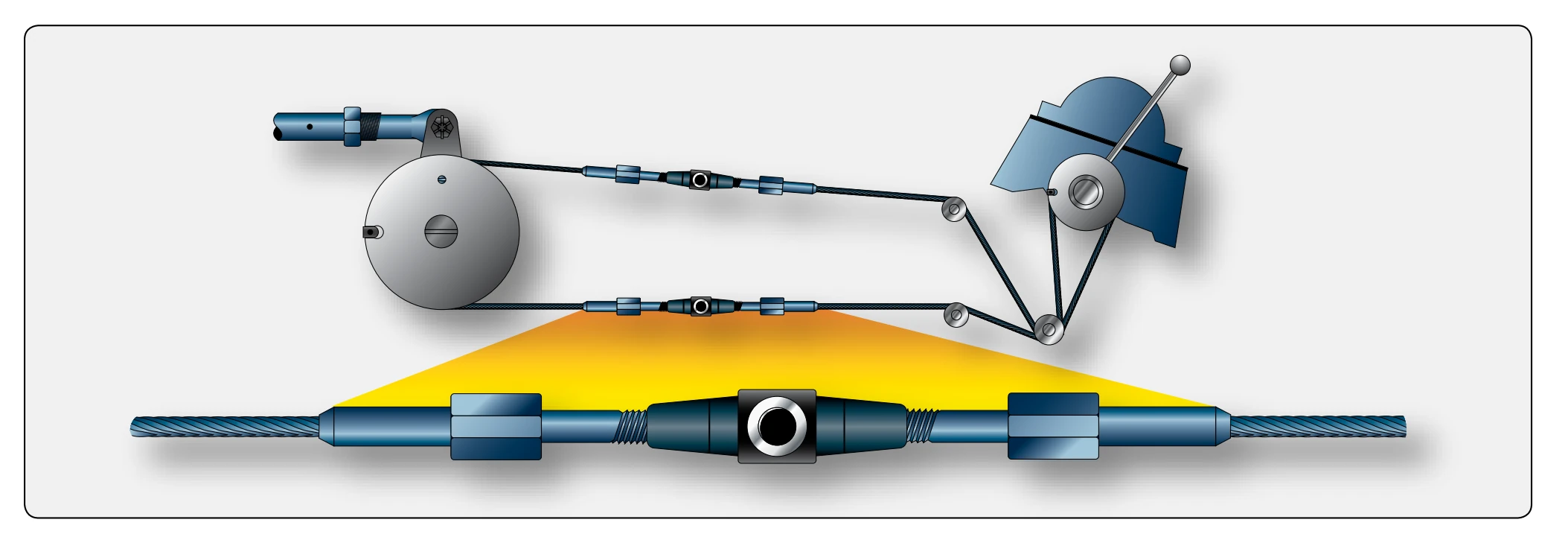
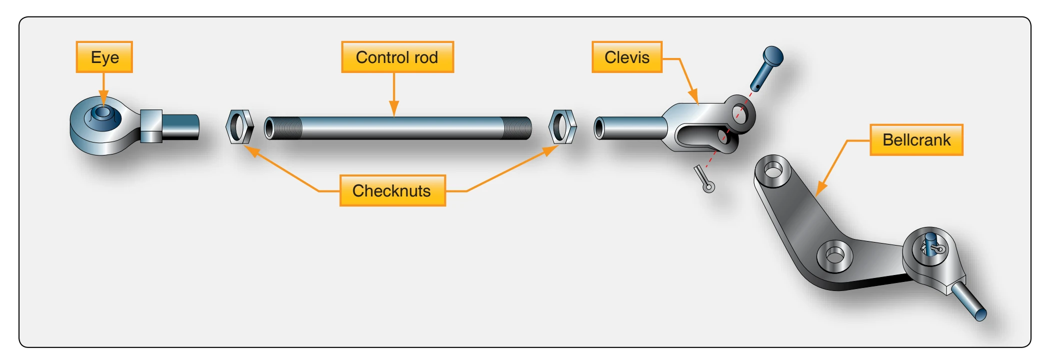
The engine control rods and cables connect such units as the carburetor or fuel control throttle valve and the mixture control valve with their manually actuated control in the flight deck. The controls are sometimes disconnected by removing the turnbuckle that joins the cable ends. [Figure 8-6] A typical reciprocating engine control linkage consisting of a control rod attached to a bell crank is illustrated in Figure 8-7.
The control rod in the linkage shown has two rod-end assemblies, a clevis, and an eye screwed onto opposite ends. These rod-end assemblies determine the length of the control rod by the distance they are screwed onto it, and they are locked into position by check nuts. An antifriction bearing is usually mounted in the eye end of a rod. This eye is slipped over a bolt in the bell crank arm and is held in position by a castle nut safety with a cotter pin. The clevis rod end is slipped over the end of a bell crank arm, which also usually contains an antifriction bearing. A bolt is passed through the clevis and the bell crank eye, fastened with a castle nut, and safetied with a cotter pin. Most control rod ends are provided with a test hole in the shank for inspection. If safety wire can be inserted through the test hole, the terminal is not being held by the required number of threads.
Sometimes linkage assemblies do not include the antifriction bearings and are held in position only by a washer and cotter pin in the end of a clevis pin that passes through the bell crank and rod end. After the engine control linkages have been disconnected, the nuts and bolts should be replaced in the rod ends or bell crank arms to prevent their being lost. All control rods should be removed completely or tied back to prevent them from being bent or broken if they are struck by the replacement engine or QECA as it is being hoisted.
Disconnection of Lines
The lines between units within the aircraft and the engine are either flexible hose or aluminum-alloy tubes joined by lengths of hose clamped to them. Lines that must withstand high pressure, such as hydraulic lines, are often made of stainless steel tubing.
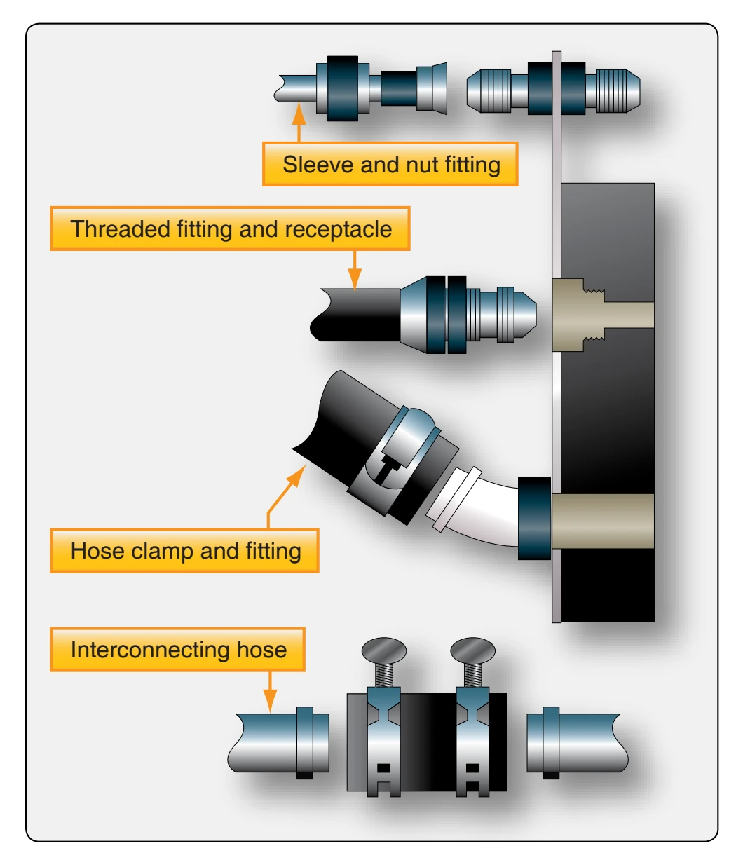
Figure 8-8 shows the basic types of line disconnects. Most lines leading from a QECA are secured to a threaded fitting at the firewall by a sleeve nut around the tubing. Hoses are sometimes secured in this manner but may also be secured by a threaded fitting on the unit to which they lead, or by a hose clamp. The firewall fittings for some lines have a quickdisconnect fitting that contains a check valve to prevent the system from losing fluid when the line is disconnected. Metal tubing on some installations may also be disconnected at a point at which two lengths of it are joined together by a length of rubber hose. Such a disconnection is made by loosening the hose clamps and sliding the length of rubber hose over the length of tubing that remains on the aircraft. There may be some further variations in these types of disconnections, but they follow the same basic pattern.
Some type of a container should be used to collect any fuel, oil, or other fluid that may drain from the disconnected lines. After the lines have drained, they should be immediately plugged or covered with moisture-proof tape to prevent foreign matter from entering them, as well as to prevent any accumulated fluid from dripping out.
Other Disconnections
The points at which the various air ducts are disconnected depend upon the engine and the aircraft in which it is installed. Usually, the air intake ducts and the exhaust system must be disconnected so the basic engine or the QECA can be removed. After the engine connections are free (except the engine mounts) and all the disconnections are entirely clear so they do not bind or become entangled, the engine can be prepared for hoisting.
Removing the Engine
If a QECA is being removed, the engine mount accompanies the engine. The mount remains on the aircraft if only the engine is being removed. Before the engine can be freed from its attachment points, a sling must be installed so the engine’s weight can be supported with a hoist when the mounting bolts are removed.
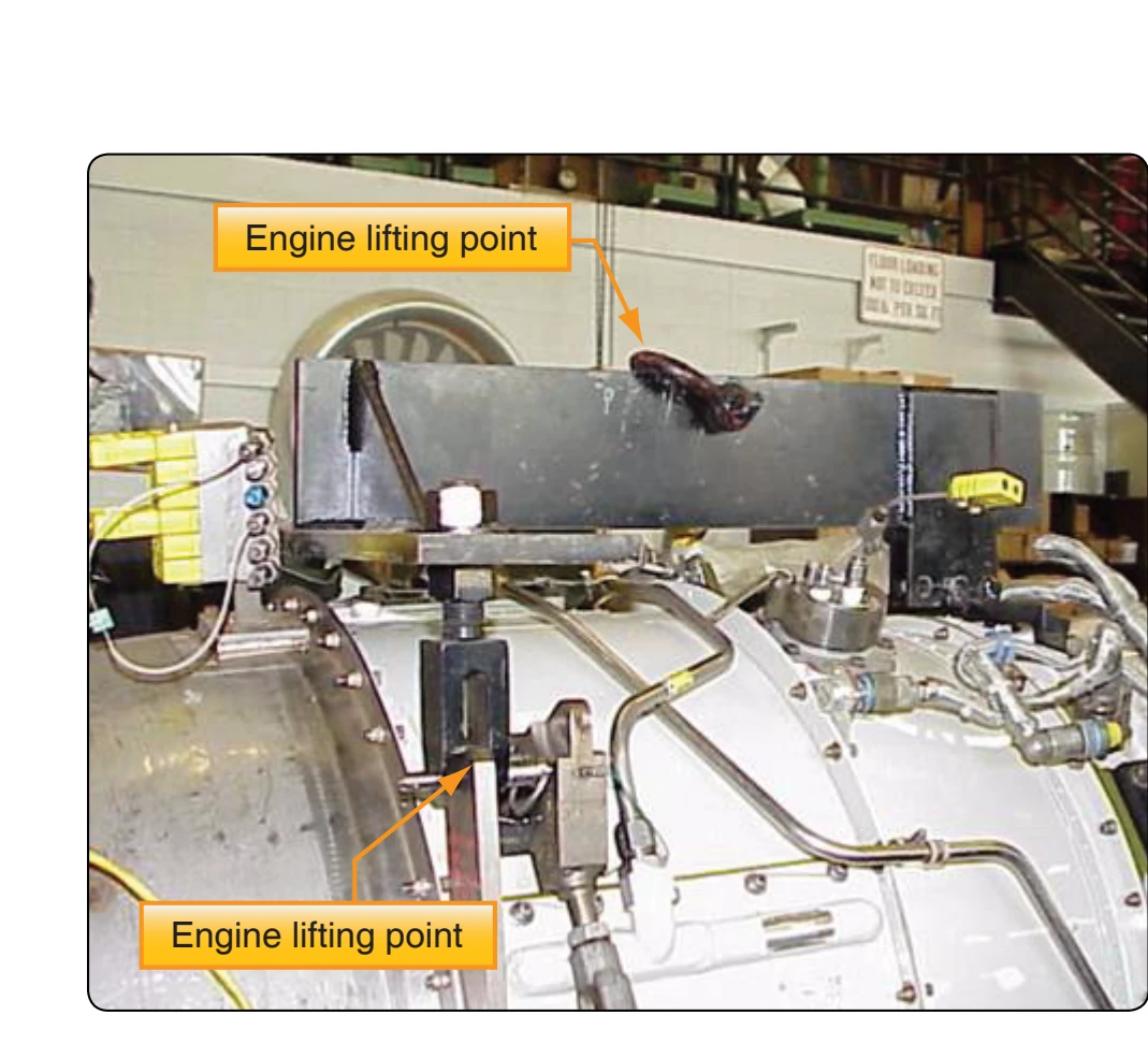
Aircraft engines, or QECAs, have marked points for attaching