
Chapter 2
Aerodynamics of Flight
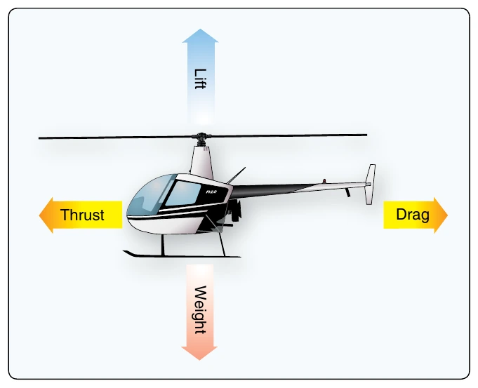
While hovering, the amount of main rotor thrust can be adjusted to maintain the desired hovering height. This is done by changing the angle of incidence (by moving the collective) of the rotor blades, and hence their AOA. Changing the AOA changes the drag on the rotor blades, and the power delivered by the engine must change as well to keep the rotor speed constant.
The weight that must be supported is the total weight of the helicopter and its occupants. If the amount of lift is greater than the actual weight, the helicopter accelerates upwards until the lift force equals the weight of the helicopter; if lift is less than weight, the helicopter accelerates downward.
The drag of a hovering helicopter is mainly induced drag incurred while the blades are producing lift. There is, however, some profile drag on the blades as they rotate through the air and a small amount of parasite drag from the non-lift-producing surfaces of the helicopter, such as the rotor hub, cowlings, and landing gear. Throughout the rest of this discussion, the term “drag” includes induced, profile and parasite drag.
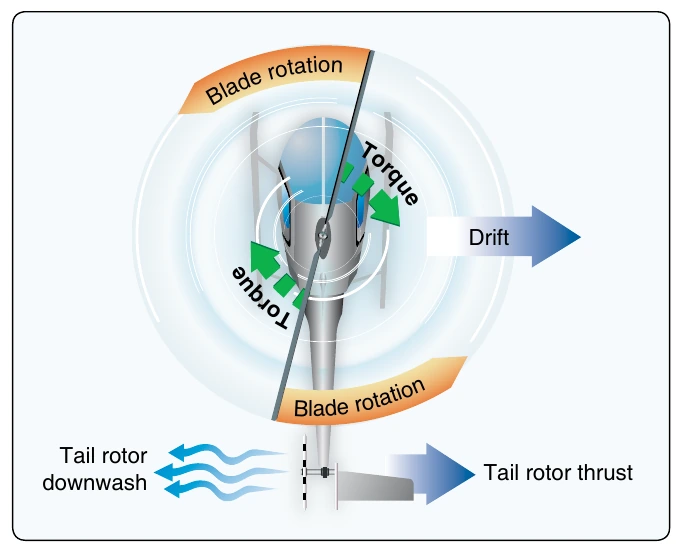
An important consequence of producing thrust is torque. As discussed earlier, Newton’s Third Law states: for every action there is an equal and opposite reaction. Therefore, as the engine turns the main rotor disk in a counterclockwise direction, the helicopter fuselage wants to turn clockwise. The amount of torque is directly related to the amount of engine power being used to turn the main rotor disk. As power changes, torque changes.
To counteract this torque-induced turning tendency, an antitorque rotor or tail rotor is incorporated into most helicopter designs. A pilot can vary the amount of thrust produced by the tail rotor in relation to the amount of torque produced by the engine. As the engine supplies more power to the main rotor, the tail rotor must produce more thrust to overcome the increased torque effect. This control change is accomplished through the use of antitorque pedals (See page 3-4).
Translating Tendency (Drift)
During hovering flight, a single main rotor helicopter tends to move in the direction of tail rotor thrust. This lateral (or sideward) movement is called translating tendency. [Figure 2-27]
To counteract this tendency, one or more of the following features may be used. All examples are for a counterclockwise rotating main rotor disk.
- The main transmission is mounted at a slight angle to the left (when viewed from behind) so that the rotor mast has a built-in tilt to oppose the tail rotor thrust.
- Flight controls can be rigged so that the rotor disk is tilted to the left slightly when the cyclic is centered. Whichever method is used, the tip-path plane is tilted slightly to the left in the hover.
- The transmission is mounted so the rotor shaft is vertical with respect to the fuselage, the helicopter “hangs” left skid low in the hover. (The opposite is true for rotor disks turning clockwise when viewed from above.)
- The helicopter fuselage will also be tilted when the tail rotor is below the main rotor disk and supplying antitorque thrust. The fuselage tilt is caused by the imperfect balance of the tail rotor thrust against the main rotor torque in the same plane. The helicopter tilts due to two separate forces, the main rotor disk tilt to neutralize the translating tendency and the lower tail rotor thrust below the plane of the torque action.
- In forward flight, the tail rotor continues to push to the right, and the helicopter makes a small angle with the wind when the rotors are level and the slip ball is in the middle (See page 12-2). This is called inherent sideslip. For some larger helicopters, the vertical fin or stabilizer is often designed with the tail rotor mounted on them to correct this side slip and to eliminate some of the tilting at a hover. (By mounting the tail rotor on top of the vertical fin or pylon, the antitorque is more in line with or closer to the horizontal plane of torque, resulting in less airframe (or body) lean from the tail rotor.) Also, having the tail rotor higher off the ground reduces the risk of objects coming in contact with the blades, but at the cost of increased weight and complexity.
Pendular Action
Since the fuselage of the helicopter, with a single main rotor, is suspended from a single point and has considerable mass, it is free to oscillate either longitudinally or laterally in the same way as a pendulum. This pendular action can be exaggerated by overcontrolling; therefore, control movements should be smooth and not exaggerated. [Figure 2-28]
The horizontal stabilizer helps to level the helicopter in forward flight. However, in rearward flight, the horizontal stabilizer can press the tail downward, resulting in a tail strike if the helicopter is moved rearward into the wind. Normally, with the helicopter mostly into the wind, the horizontal stabilizer experiences less headwind component as the helicopter begins rearward travel (downwind). When rearward flight groundspeed equals the windspeed, then the helicopter is merely hovering in a no-wind condition. However, rearward hovering into the wind requires considerable care and caution to prevent tail strikes.
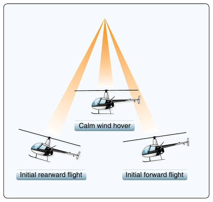
It is important to note that there is a difference in the amount of pendular action between a semirigid system and a fully articulated system. Because of the hard connection (offset) of the latter, the centrifugal force pulling out on the blades is transferred to the fuselage, and the fuselage tends to follow the rotor attitude. The semirigid system is a true pendulum, with thrust required to create a moment around the fuselage CG to allow for control of the fuselage. This comes into play later when mast bumping is discussed.
Coning
In order for a helicopter to generate lift, the rotor blades must be turning. Rotor disk rotation drives the blades into the air, creating a relative wind component without having to move the airframe through the air as with an airplane or glider. Depending on the motion of the blades and helicopter airframe, many factors cause the relative wind direction to vary. The rotation of the rotor disk creates centrifugal force (inertia), which tends to pull the blades straight outward from the main rotor hub: the faster the rotation, the greater the centrifugal force, the slower the rotation, the smaller the centrifugal force. This force gives the rotor blades their rigidity and, in turn, the strength to support the weight of the helicopter. The maximum centrifugal force generated is determined by the maximum operating rotor revolutions per minute (rpm).
As lift on the blades is increased (in a takeoff, for example), two major forces are acting at the same time—centrifugal force acting outward, and lift acting upward. The result of these two forces is that the blades assume a conical path instead of remaining in the plane perpendicular to the mast. This can be seen in any helicopter when it takes off; the rotor disk changes from flat to a slight cone shape. [Figure 2-29]
If the rotor rpm is allowed to go too low (below the minimum power-on rotor rpm, for example), the centrifugal force becomes smaller and the coning angle becomes much larger. In other words, should the rpm decrease too much, at some point the rotor blades fold up with no chance of recovery.