
Chapter 10
IFR Flight
- 3° per second, or
- 30° bank angle, or
- A bank angle provided by a flight director system.
Time Factors
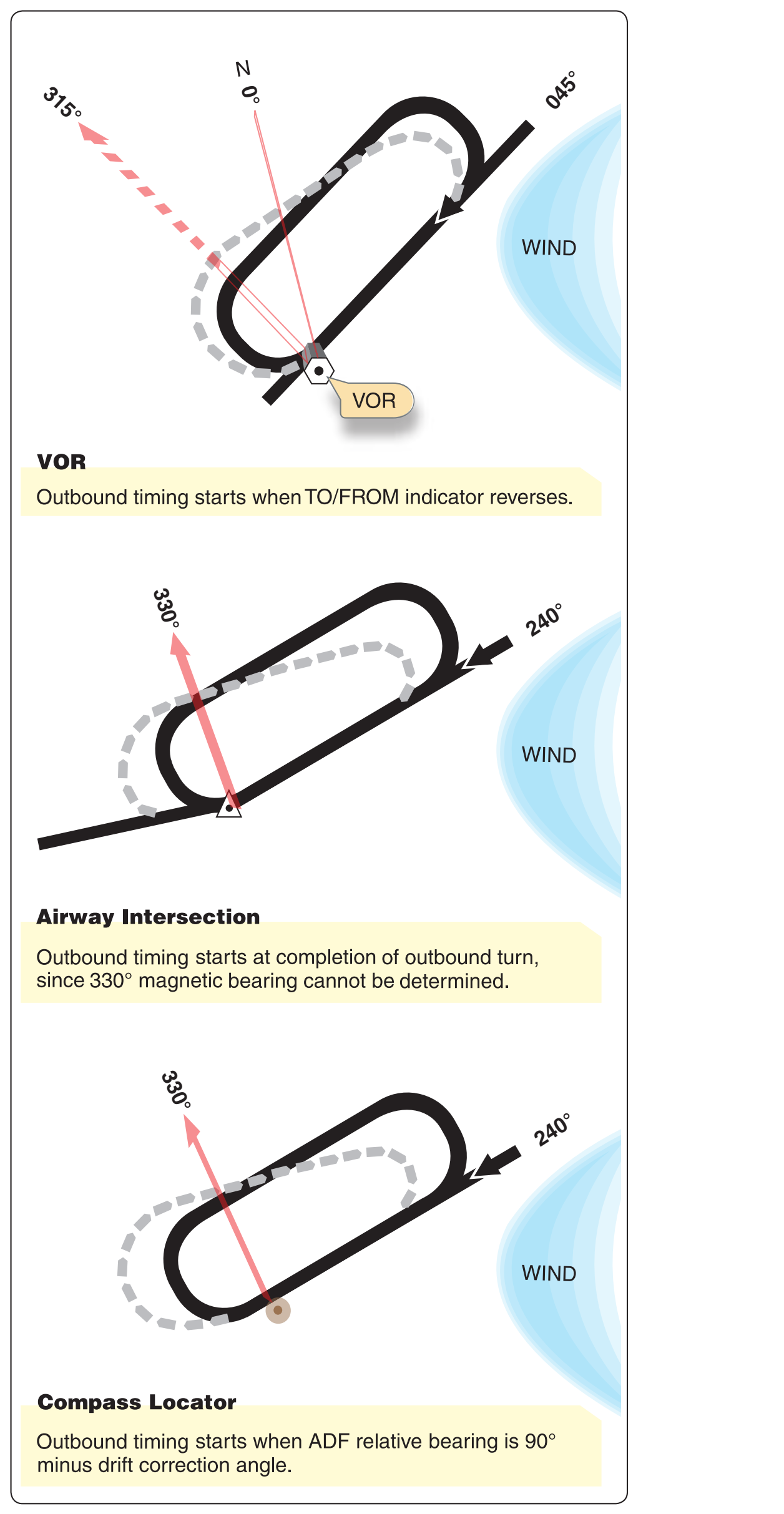
The holding pattern entry time reported to ATC is the initial time of arrival over the fix. Upon entering a holding pattern, the initial outbound leg is flown for 1 minute at or below 14,000 feet MSL, and for 1 ⁄ minutes above 14,000 feet MSL. Timing for subsequent outbound legs should be adjusted as necessary to achieve proper inbound leg time. The pilot should begin outbound timing over or abeam the fix, whichever occurs later. If the abeam position cannot be determined, start timing when the turn to outbound is completed. [Figure 10-7] Time leaving the holding fix must be known to ATC before succeeding aircraft can be cleared to the vacated airspace. Leave the holding fix:
- When ATC issues either further clearance en route or approach clearance;
- As prescribed in 14 CFR part 91 (for IFR operations; two-way radio communications failure, and responsibility and authority of the pilot-in-command); or
- After the IFR flight plan has been cancelled, if the aircraft is holding in VFR conditions.
DME Holding
The same entry and holding procedures apply to DME holding, but distances (nautical miles) are used instead of time values. The length of the outbound leg is specified by the controller, and the end of this leg is determined by the DME readout.
Approaches
Compliance With Published Standard Instrument Approach Procedures
Compliance with the approach procedures shown on the approach charts provides necessary navigation guidance information for alignment with the final approach courses, as well as obstruction clearance. Under certain conditions, a course reversal maneuver or procedure turn may be necessary. However, this procedure is not authorized when:
- The symbol “NoPT” appears on the approach course on the plan view of the approach chart.
- Radar vectoring is provided to the final approach course.
- A holding pattern is published in lieu of a procedure turn.
- Executing a timed approach from a holding fix.
- Otherwise directed by ATC.
Instrument Approaches to Civil Airports
Unless otherwise authorized, when an instrument letdown to an airport is necessary, the pilot should use a standard IAP prescribed for that airport. IAPs are depicted on IAP charts and are found in the TPP.
ATC approach procedures depend upon the facilities available at the terminal area, the type of instrument approach executed, and the existing weather conditions. The ATC facilities, NAVAIDs, and associated frequencies appropriate to each standard instrument approach are given on the approach chart. Individual charts are published for standard approach procedures associated with the following types of facilities:
- Nondirectional beacon (NDB)
- Very-high frequency omnirange (VOR)
- Very-high frequency omnirange with distance measuring equipment (VORTAC or VOR/DME)
- Localizer (LOC)
- Instrument landing system (ILS)
- Localizer-type directional aid (LDA)
- Simplified directional facility (SDF)
- Area navigation (RNAV)
- Global positioning system (GPS)
An IAP can be flown in one of two ways: as a full approach or with the assistance of radar vectors. When the IAP is flown as a full approach, pilots conduct their own navigation using the routes and altitudes depicted on the instrument approach chart. A full approach allows the pilot to transition from the en route phase, to the instrument approach, and then to a landing with minimal assistance from ATC. This type of procedure may be requested by the pilot but is most often used in areas without radar coverage. A full approach also provides the pilot with a means of completing an instrument approach in the event of a communications failure.
When an approach is flown with the assistance of radar vectors, ATC provides guidance in the form of headings and altitudes, which position the aircraft to intercept the final approach. From this point, the pilot resumes navigation, intercepts the final approach course, and completes the approach using the IAP chart. This is often a more expedient method of flying the approach, as opposed to the full approach, and allows ATC to sequence arriving traffic. A pilot operating in radar contact can generally expect the assistance of radar vectors to the final approach course.
Approach to Airport Without an Operating Control Tower
Figure 10-8 shows an approach procedure at an airport without an operating control tower. When approaching such a facility, the pilot should monitor the AWOS/ASOS if available for the latest weather conditions. When direct communication between the pilot and controller is no longer required, the ARTCC or approach controller issues a clearance for an instrument approach and advises “change to advisory frequency approved.” When the aircraft arrives on a “cruise” clearance, ATC does not issue further clearance for approach and landing.
If an approach clearance is required, ATC authorizes the pilots to execute his or her choice of standard instrument approach (if more than one is published for the airport) with the phrase “Cleared for the approach” and the communications frequency change required, if any. From this point on, there is no contact with ATC. The pilot is responsible for closing the IFR flight plan before landing, if in VFR conditions, or by telephone after landing.