Chapter 7
Airplane Basic Flight Maneuvers
Unlike older analog VSIs, new glass panel displays have instantaneous VSIs. Older units had a lag designed into the system that was utilized to indicate rate information. The new glass panel displays utilize a digital air data computer that does not indicate a lag. Altitude changes are shown immediately and can be corrected for quickly.
The VSI tape should be used to assist in determining what pitch changes are necessary to return to the desired altitude. A good rule of thumb is to use a vertical speed rate of change that is double the altitude deviation. However, at no time should the rate of change be more than the optimum rate of climb or descent for the specific aircraft being flown. For example, if the altitude is off by 200 feet from the desired altitude, then a 400 feet per minute (fpm) rate of change would be sufficient to get the aircraft back to the original altitude. If the altitude has changed by 700 feet, then doubling that would necessitate a 1,400 fpm change. Most aircraft are not capable of that, so restrict changes to no more than optimum climb and descent. An optimum rate of change would vary between 500 and 1,000 fpm.
One error the instrument pilot encounters is overcontrolling. Overcontrolling occurs when a deviation of more than 200 fpm is indicated over the optimum rate of change. For example, an altitude deviation of 200 feet is indicated on the altimeter, a vertical speed rate of 400 feet should be indicated on the gauge. If the vertical speed rate showed 600 fpm (200 more than optimum), the pilot would be overcontrolling the aircraft.
When returning to altitude, the primary pitch instrument is the VSI tape. If any deviation from the desired vertical speed is indicated, make the appropriate pitch change using the attitude indicator.
As the aircraft approaches the target altitude, the vertical speed rate can be slowed in order to capture the altitude in a more stabilized fashion. Normally within 10 percent of the rate of climb or descent from the target altitude, begin to slow the vertical speed rate in order to level off at the target altitude. This allows the pilot to level at the desired altitude without rapid control inputs or experiencing discomfort due to G-load.
Airspeed Indicator (ASI)
The ASI presents an indirect indication of the pitch attitude. At a constant power setting and pitch attitude, airspeed remains constant. As the pitch attitude lowers, airspeed increases, and the nose should be raised.
As the pitch attitude is increased, the nose of the aircraft raises, which results in an increase in the angle of attack as well as an increase in induced drag. The increased drag begins to slow the momentum of the aircraft, which is indicated on the ASI. The airspeed trend indicator shows a trend as to where the airspeed will be in 6 seconds. Conversely, if the nose of the aircraft should begin to fall, the angle of attack, as well as induced drag, decreases.
There is a lag associated with the ASI when using it as a pitch instrument. It is not a lag associated with the construction of the ASI, but a lag associated with momentum change. Depending on the rate of momentum change, the ASI may not indicate a pitch change in a timely fashion. If the ASI is being used as the sole reference for pitch change, it may not allow for a prompt correction. However, if smooth pitch changes are executed, modern glass panel displays are capable of indicating 1 knot changes in airspeed and also capable of projecting airspeed trends.
When flying by reference to flight instruments alone, it is imperative that all of the flight instruments be cross-checked for pitch control. By cross-checking all pitch related instruments, the pilot can better visualize the aircraft attitude at all times.
As previously stated, the primary instrument for pitch is the instrument that gives the pilot the most pertinent information for a specific parameter. When in level flight and maintaining a constant altitude, what instrument shows a direct indication of altitude? The only instrument that is capable of showing altitude is the altimeter. The other instruments are supporting instruments that are capable of showing a trend away from altitude, but do not directly indicate an altitude.
The supporting instruments forewarn of an impending altitude deviation. With an efficient cross-check, a proficient pilot is better able to maintain altitude.
Bank Control
This discussion assumes the aircraft is being flown in coordinated flight, which means the longitudinal axis of the aircraft is aligned with the relative wind. On the PFD, the attitude indicator shows if the wings are level. The turn rate indicator, slip/skid indicator, and the heading indicator also indicate whether or not the aircraft is maintaining a straight (zero bank) flightpath.
Attitude Indicator
The attitude indicator is the only instrument on the PFD that has the capability of displaying the precise bank angle of the aircraft. This is made possible by the display of the roll scale depicted as part of the attitude indicator.
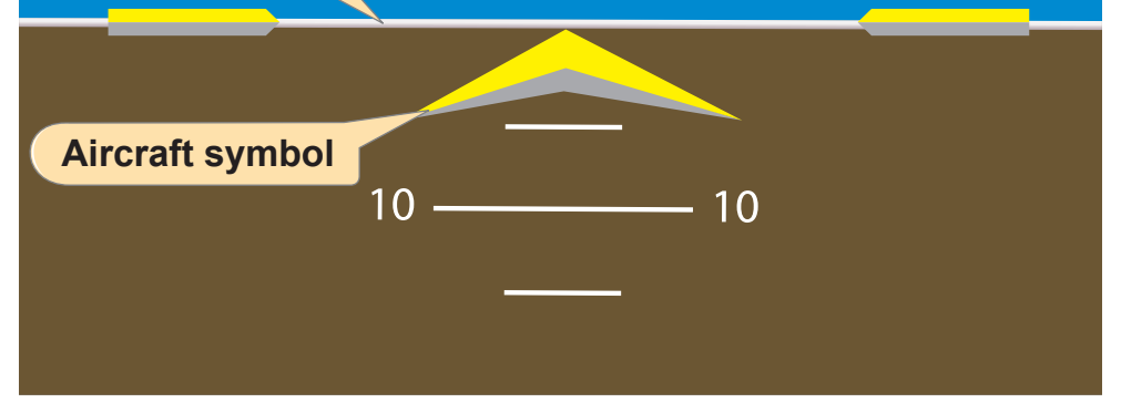
Figure 7-52 identifies the components that make up the attitude indicator display. Note that the top of the display is blue, representing sky, the bottom is brown, depicting dirt, and the white line separating them is the horizon. The lines parallel to the horizon line are the pitch scale, which is marked in 5 degree increments and labeled every 10 degrees. The pitch scale always remains parallel to the horizon.
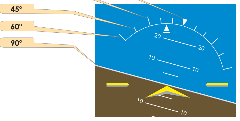
The curved line in the blue area is the roll scale. The triangle on the top of the scale is the zero index. The hash marks on the scale represent the degree of bank. [Figure 7-53] The roll scale always remains in the same position relative to the horizon line.