Chapter 7
Airplane Basic Flight Maneuvers
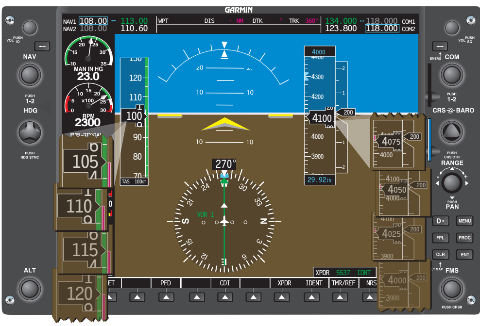
The roll pointer indicates the direction and degree of bank. [Figure 7-53] The roll pointer is aligned with the aircraft symbol. The roll pointer indicates the angle of the lateral axis of the aircraft compared to the natural horizon. The slip/skid indicator will show if the longitudinal axis of the aircraft is aligned with the relative wind, which is coordinated flight. With the roll index and the slip/skid indicator aligned, any deflection, either right or left of the roll index causes the aircraft to turn in that direction. With the small graduations on the roll scale, it is easy to determine the bank angle within approximately 1 degree. In coordinated flight, if the roll index is aligned with the roll pointer, the aircraft is achieving straight flight.
An advantage of EFDs is the elimination of the precession error. Precession error in analog gauges is caused by forces being applied to a spinning gyro. With the new solid state instruments, precession error has been eliminated.
Since the attitude indicator is capable of showing precise pitch and bank angles, the only time that the attitude indicator is a primary instrument is when attempting to fly at a specific bank angle or pitch angle. Other times, the attitude instrument can be thought of as a control instrument.
Horizontal Situation Indicator (HSI)
The horizontal situation indicator (HSI) is a rotating 360° compass card that indicates magnetic heading. The HSI is the only instrument that is capable of showing exact headings. The magnetic compass can be used as a backup instrument in case of an HSI failure; however, due to erratic, unstable movements, it is more likely to be used a supporting instrument.
In order for the pilot to achieve the desired rate of change, it is important for him or her to understand the relationship between the rate at which the HSI changes heading displays and the amount of bank angle required to meet that rate of change. A very small rate of heading change means the bank angle is small, and it takes more time to deviate from the desired straight flightpath. A larger rate of heading change means a greater bank angle happens at a faster rate.
Heading Indicator
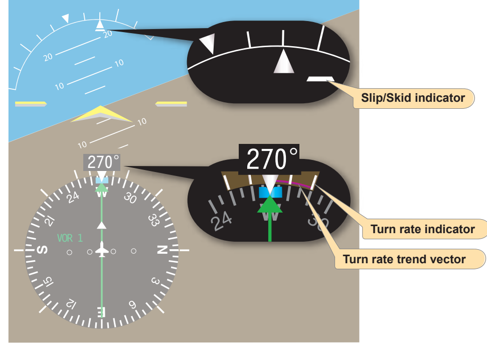
The heading indicator is the large black box with a white number that indicates the magnetic heading of the aircraft. [Figure 7-54] The aircraft heading is displayed to the nearest degree. When this number begins to change, the pilot should be aware that straight flight is no longer being achieved.
Turn Rate Indicator
The turn rate indicator gives an indirect indication of bank. It is a magenta trend indicator capable of displaying half-standard as well as standard rate turns to both the left and right. [Figure 7-54] The turn indicator is capable of indicating turns up to 4 degrees per second by extending the magenta line outward from the standard rate mark. If the rate of turn has exceeded 4 degrees per second, the magenta line can not precisely indicate where the heading will be in the next 6 seconds; the magenta line freezes and an arrowhead will be displayed. This alerts the pilot to the fact that the normal range of operation has been exceeded.
Slip/Skid Indicator
The slip/skid indicator is the small portion of the lower segmented triangle displayed on the attitude indicator. This instrument depicts whether the aircraft’s longitudinal axis is aligned with the relative wind. [Figure 7-54]
The pilot must always remember to cross-check the roll index to the roll pointer when attempting to maintain straight flight. Any time the heading remains constant and the roll pointer and the roll index are not aligned, the aircraft is in uncoordinated flight. To make a correction, the pilot should apply rudder pressure to bring the aircraft back to coordinated flight.
Power Control
Power produces thrust which, with the appropriate angle of attack of the wing, overcomes the forces of gravity, drag, and inertia to determine airplane performance.
Power control must be related to its effect on altitude and airspeed, since any change in power setting results in a change in the airspeed or the altitude of the airplane. At any given airspeed, the power setting determines whether the airplane is in level flight, in a climb, or in a descent. If the power is increased in straight-and-level flight and the airspeed held constant, the airplane climbs; if power is decreased while the airspeed is held constant, the airplane descends. On the other hand, if altitude is held constant, the power applied determines the airspeed.
The relationship between altitude and airspeed determines the need for a change in pitch or power. If the airspeed is off the desired value, always check the altimeter before deciding that a power change is necessary. Think of altitude and airspeed as interchangeable; altitude can be traded for airspeed by lowering the nose, or convert airspeed to altitude by raising the nose. If altitude is higher than desired and airspeed is low, or vice versa, a change in pitch alone may return the airplane to the desired altitude and airspeed. [Figure 7-55] If both airspeed and altitude are high or if both are low, then a change in both pitch and power is necessary in order to return to the desired airspeed and altitude. [Figure 7-56]
For changes in airspeed in straight-and-level flight, pitch, bank, and power must be coordinated in order to maintain constant altitude and heading. When power is changed to vary airspeed in straight-and-level flight, a single-engine, propeller-driven airplane tends to change attitude around all axes of movement. Therefore, to maintain constant altitude and heading, apply various control pressures in proportion to the change in power. When power is added to increase airspeed, the pitch instruments indicate a climb unless forward-elevator control pressure is applied as the airspeed changes. With an increase in power, the airplane tends to yaw and roll to the left unless counteracting aileron and rudder pressures are applied. Keeping ahead of these changes requires increasing cross-check speed, which varies with the type of airplane and its torque characteristics, the extent of power and speed change involved.