Chapter 1
Departure Procedures
Ceiling and Visibility Requirements
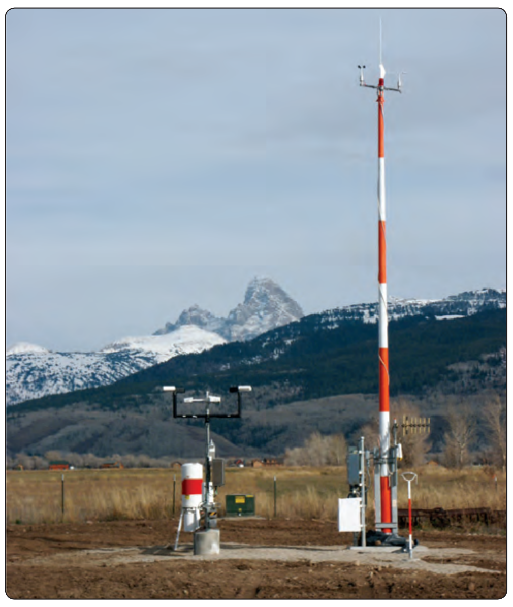
All takeoffs and departures have visibility minimums (some may have minimum ceiling requirements) incorporated into the procedure. There are a number of methods to report visibility and a variety of ways to distribute these reports, including automated weather observations. Flight crews should always check the weather, including ceiling and visibility information, prior to departure. Never launch an IFR flight without obtaining current visibility information immediately prior to departure. Further, when ceiling and visibility minimums are specified for IFR departure, both are applicable.
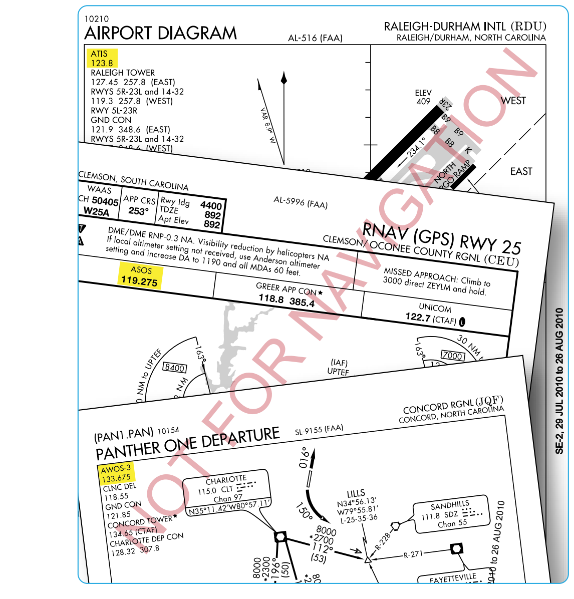
Weather reporting stations for specific airports across the country can be located by reviewing the CS. Weather sources along with their respective phone numbers and frequencies are listed by airport. Frequencies for weather sources, such as Automatic Terminal Information Service (ATIS), Digital Automatic Terminal Information Service (D-ATIS), Automated Weather Observing System (AWOS), Automated Surface Observing System (ASOS), and FAA Automated Flight Service Station (AFSS) are published on approach charts as well. [Figure 1-9]
Visibility
Visibility is the ability, as determined by atmospheric conditions and expressed in units of distance, to see and identify prominent unlighted objects by day and prominent lighted objects by night. Visibility is reported as statute miles, hundreds of feet, or meters.
Prevailing Visibility
Prevailing visibility is the greatest horizontal visibility equaled or exceeded throughout at least half the horizon circle, which need not necessarily be continuous. Prevailing visibility is reported in statute miles or fractions of miles.
Runway Visibility Value (RVV)
Runway visibility value is the visibility determined for a particular runway by a transmissometer. A meter provides continuous indication of the visibility (reported in statute miles or fractions of miles) for the runway. RVV is used in lieu of prevailing visibility in determining minimums for a particular runway.
Tower Visibility
Tower visibility is the prevailing visibility determined from the airport traffic control tower at locations that also report the surface visibility.
Runway Visual Range (RVR)
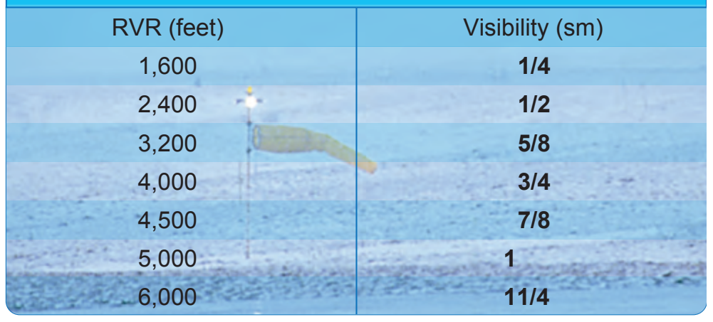
Runway visual range is an instrumentally derived value, based on standard calibrations, that represents the horizontal distance a pilot sees down the runway from the approach end. It is based on the sighting of either high intensity runway lights or on the visual contrast of other targets, whichever yields the greater visual range. RVR, in contrast to prevailing or runway visibility, is based on what a pilot in a moving aircraft should see looking down the runway. RVR is horizontal visual range, not slant visual range. RVR is reported in hundreds of feet, so the values must be converted to SM if the visibility in SM is not reported. [Figure 1-10] It is based on the measurement of a transmissometer made near the touchdown point of the instrument runway and is reported in hundreds of feet. RVR is used in lieu of RVV and/or prevailing visibility in determining minimums for a particular runway.
Types of RVR The following are types of RVR that may be used:
- Touchdown RVR—the RVR visibility readout values obtained from RVR equipment serving the runway touchdown zone.
- Mid-RVR—the RVR readout values obtained from RVR equipment located near the runway midpoint.
- Rollout RVR—the RVR readout values obtained from RVR equipment located nearest the rollout end of the runway.
- Far End RVR—when four RVR visibility sensors (VS) are installed, the far end RVR VS is the touchdown RVR VS on the reciprocal runway. The far end sensor will serve as additional information.
RVR is the primary visibility measurement used by Part 121 and Part 135 operators with specific visibility reports and controlling values outlined in their respective OpSpecs. Under their OpSpecs agreements, the operator must have specific, current RVR reports, if available, to proceed with an instrument departure. OpSpecs also outline which visibility report is controlling in various departure scenarios.