Chapter 4
Operations
Bridle Length
The length of the bridle has an effect primarily on the deployment of the main pilot chute itself. In the case of a throw-out pilot chute, the bridle must be long enough to get the deployed pilot chute out of the turbulence in the wake of the jumper’s back. If the bridle is too short, the pilot chute stays in the parachutist’s burble. The length of the bridle from the locking pin to the pilot chute averages around 7 feet.
Recent years have seen the growth of the use of the “birdman” flying suits or wingsuits. Because of the increased surface area and the decreased free fall speeds, the use of a longer bridle has become common, with a 9-foot length working well. Along with the longer bridle, containers have been modified to allow the bottom to open fully and the main bag to be extracted rearward towards the feet due to the more horizontal trajectory of the parachutist. Some manufacturers have also reoriented the mouth of the main deployment bag for wingsuiters so that the lines are sitting on the floor of the container tray rather than the bottom flap. This way the bag rotates 90° out of the container rather than 180°.
In the case of a pull-out pilot chute, where the jumper actually pulls the pin, the pilot chute is placed with an arc motion of the arm in the fast air near his or her head so as to avoid the burble. The jumper’s grip on the pull-out handle is gradually released as they rotate into a head-high position, reducing the size of the burble, and in preparation for opening.
Rubber Bands
The rubber stow bands play an important part in the deployment sequence and serve two important functions. First, they hold the mouth of the deployment bag closed and prevent premature deployment of the main canopy. Secondly, they hold the line stows securely to allow a clean, orderly deployment of the lines. With the advent of smaller diameter lines, such as 550 or 725 Spectra® and HMA®, smaller diameter rubber bands have been developed to properly secure these lines. If the smaller rubber bands are not available, many parachutists double stow the larger rubber bands around the small lines.
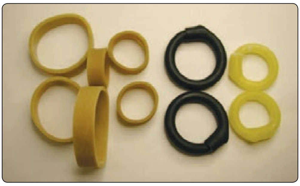
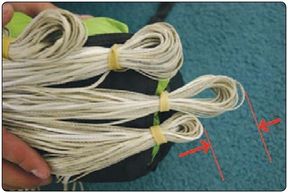
There are other products, which are designed to replace rubber bands and last longer, but they have downsides. Rubber bands other than military standard (Mil Spec) rubber bands may not break at the desired 40–45 pounds and can lead to bag locks. Other products may not have enough retention ability and allow the lines to “dump.” Figure 4-38 shows the various rubber bands and Tube Stoes®. In addition to the correct rubber bands, the length of the line stows is important as well. In the past, 1-inch stows were common, but today 3-inch stows are recommended by several manufacturers. Figure 4-39 shows the comparison between the two lengths. The main point to remember is that the lines must be stowed neatly and securely.
Assembly of the Main Canopy To The Harness and Container
The rigger should be familiar with the various types of canopy releases currently in use. In skydiving, the most common release is the 3-ring release system. It was originally developed in 1976 for skydiving, but has since become the dominant release system for intentional jumping, both civilian and military.
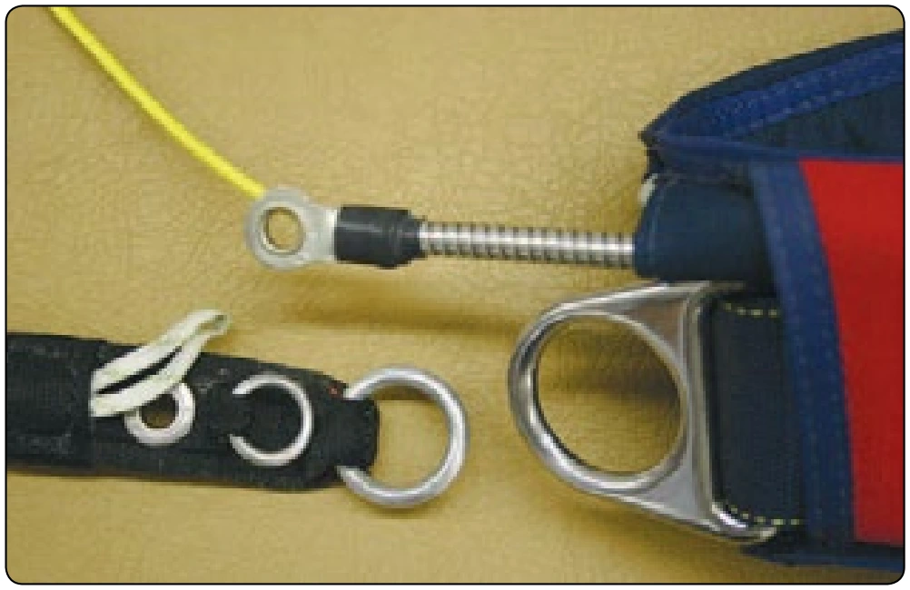
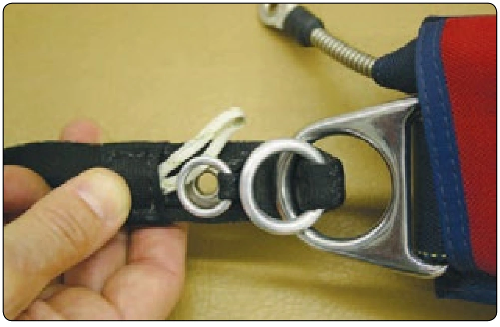
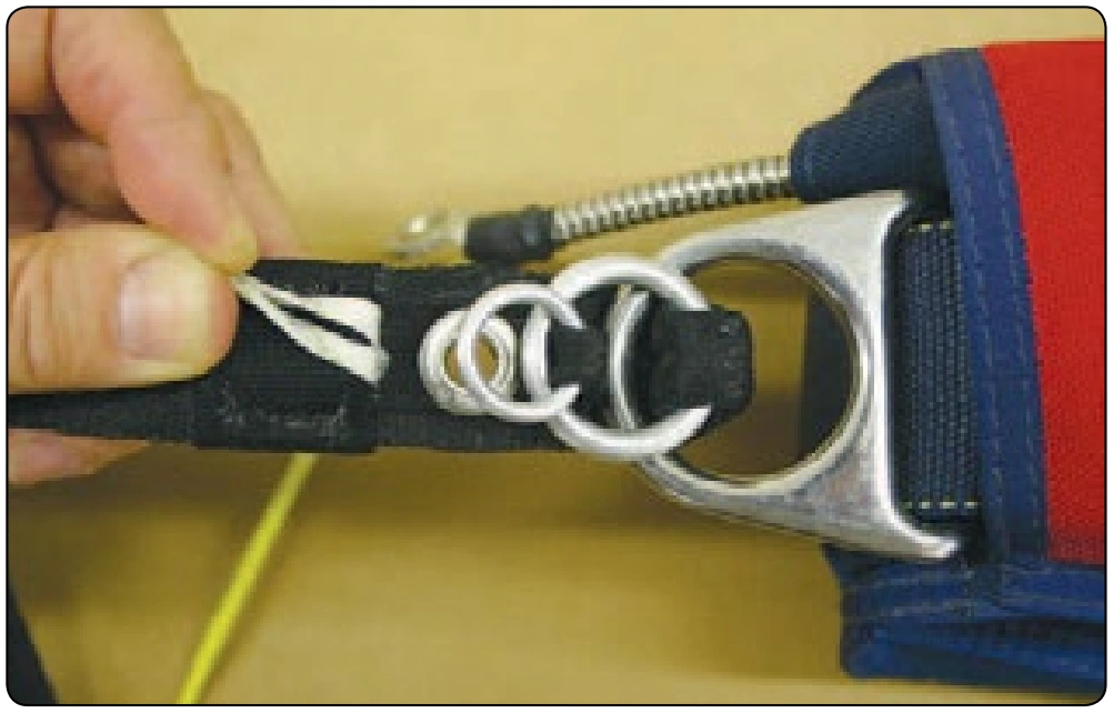
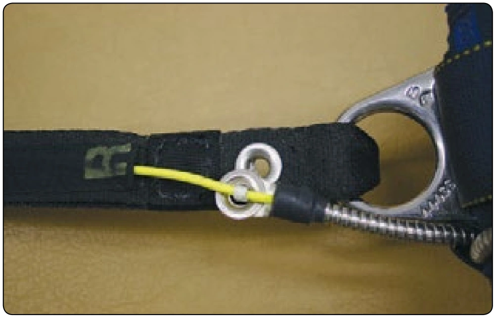
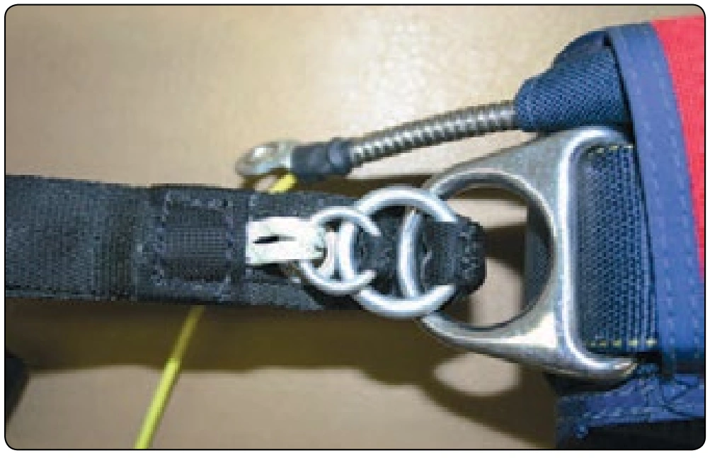
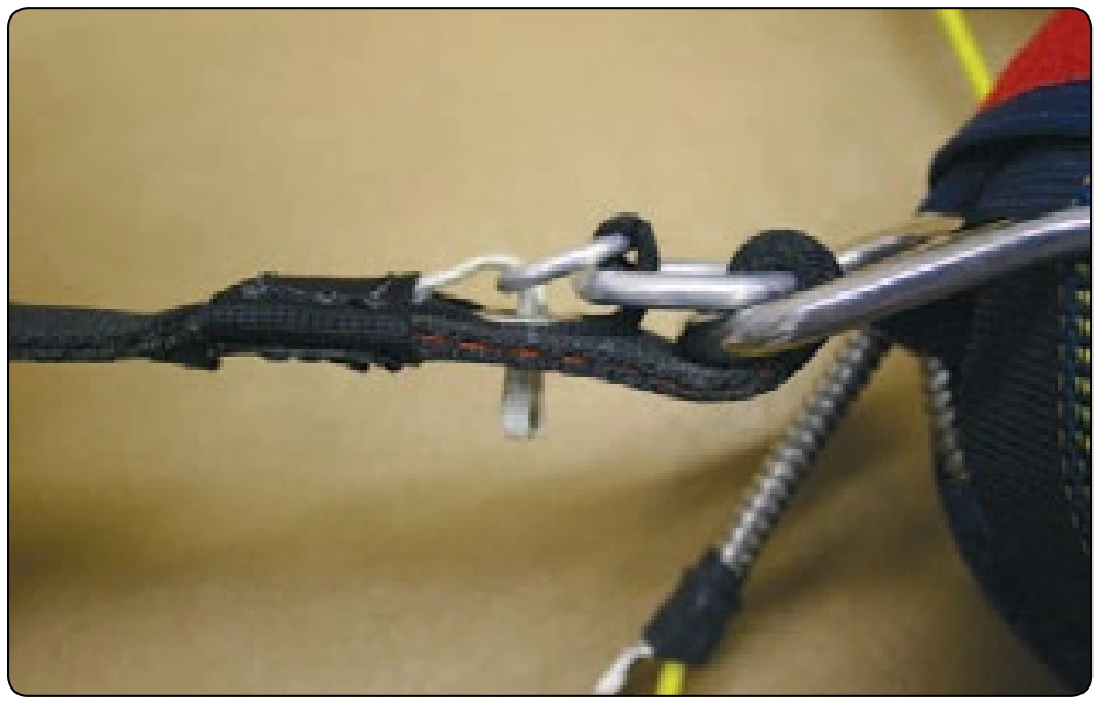
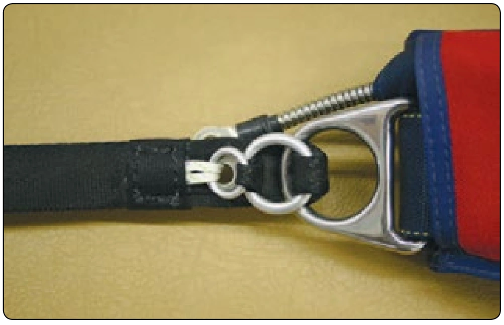
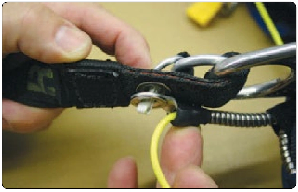
Riggers must be familiar with the assembly of the 3-ring release since they may have to connect new canopies to the harness and container or have to disconnect the main canopy to untangle it after landing. Shown in Figures 4-40 through 4-47 is the correct assembly sequence. The rigger must also be able to inspect the 3-ring release to determine any wear. In particular, the following areas need to be inspected: