Chapter 5
Inspection and Packing
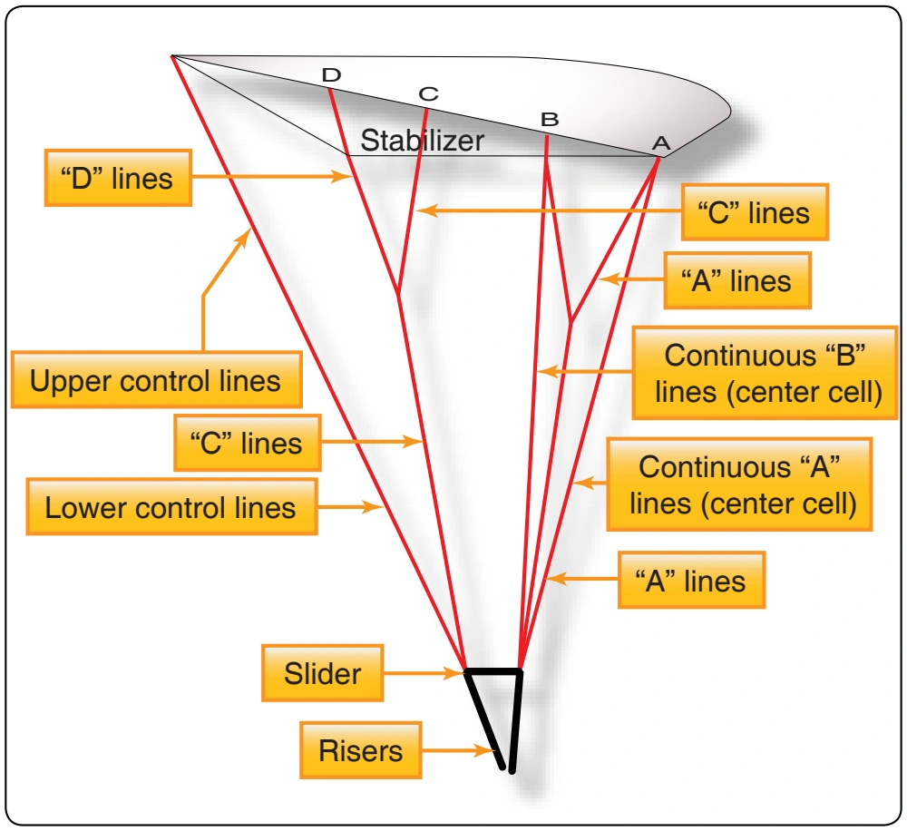
- Turn the container over, harness down, and orient the rear risers to receive their respective links. This simplifies C/D link attachment.
- Rotate the leading edge under the rest of the canopy. Split the aft section along with its associated control line groups to make the C/D links easily accessible for routing and installation.
- Locate the data panel at the center cell’s upper surface trailing edge. From this center reference point, follow the trailing edge to the left stabilizer and pick up line 1D.
- Route this line to the outboard side of its link and attach the link to the left rear riser, finger tight.
- Again from the center reference, follow the trailing edge to the right stabilizer and pick up line 8D (10D).
- Route this line to the outboard side of its link and attach the link to the right rear riser, finger tight.
- Return to the center reference point of the trailing edge. Locate and pick up the left side upper control lines consecutively. Verify their continuity to the junction with the lower control line.
- Removing twists as you go, follow the left lower control line to its running end. Route it through the appropriate slider grommet and then through the guide ring.
- Remove the toggle from the riser and route the running end of the lower control line through the toggle attachment loop or grommet.
- Slide the toggle up to the mark on the control line. Secure it with an overhand knot tied closely to the toggle.
- The control line attachment for the right side is done in a similar manner.
- When the control line installation is complete, compare the two toggle settings under equal tension to ensure their uniformity.
- At this time, verify the continuity of the control line system. Begin at the trailing edge on each side, ensuring that all twists have been removed from the upper and lower control lines. Check that the lower control lines have been properly routed through their appropriate slider grommets and that the toggles have been properly secured equidistant from the trailing edge.
- Separate the aft section and control line groups to their respective sides and locate the center reference point at the trailing edge.
- Following the trailing edge control surface outboard leads the rigger to the left stabilizer’s bottom seam and the attachment point of line 1D.
- Holding D lines 1,2,3, and 4 (1,2,3,4,5) in your right hand and D lines 5,6,7, and 8 (6,7,8,9,10) in your left hand, verify the continuity of the C and D lines through the cascades to their respective rear risers.
- Gather in the control lines and flip the canopy over so the leading edge faces up. Verify this orientation by locating the attachment points of A lines 1 and 8 (10).
- In the same direction you flipped the canopy, rotate the container system harness up.
- Pick up the front riser groups, follow them to the canopy, and separate.
- Pick up A lines 8,7,6, and 5 (10, 9,8,7,6). If you have continuous center cell lines, follow the bottom seam down and pick up line 5B (6B). Verify continuity of the A and B lines, through the cascades, to the right front riser.
- Pick up A lines 1,2,3, and 4 (and 5). If you have continuous center cell lines, follow the bottom seam down and pick up line 4B (5B). Verify continuity through the cascades to the left front riser. The continuity check is now complete.
- Tighten the connector links with an appropriate size wrench. Do not over tighten. Inspect the links for any marks or damage possibly done during the tightening process. Mark the barrel of the connector links with a telltale mark.
- Move the slider upward from the risers onto the suspension lines.
- Move the slider bumpers upwards and into position over the connector links. Hand tack the bumpers in place according to the type used.
Inspection
- Starting at the lower surface of the canopy, check the line attachment loops and their associated bar tacks. Follow the line downward to the cascade junction, if applicable, and check the bar tack at this location.
Continue down the line to the connector links and check the bottom loop and bar tack.
- Starting at the top and working your way downward, inspect the steering lines. Check all junctions and bar tacks, paying particular attention to the brake loops. Check the security of the steering toggles to ensure the correct attachment method is followed. If the toggles are improperly tied, they may come off when the jumper deploys the brakes. Make sure the toggle matches the size of the brake loops. If they are too large, they may hang up and not release when needed. For compatibility, the toggles should be those supplied with the harness and container.
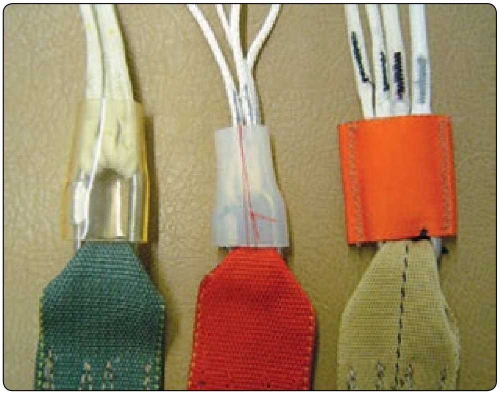
- If Rapide® links are used on the canopy, check them as set forth in the section on round canopies. The link orientation and tightness is the same. Some canopy manufacturers provide and prescribe the use of “slider bumpers” with their canopies. These are made from either webbing or from vinyl or rubber tubing and are designed to protect the grommets of the slider from impacting the connector links during deployment. If these bumpers are used, it is recommended that they be tacked in such a manner that they cannot slide up the lines and interfere with the slider during deployment. [Figure 5-24]
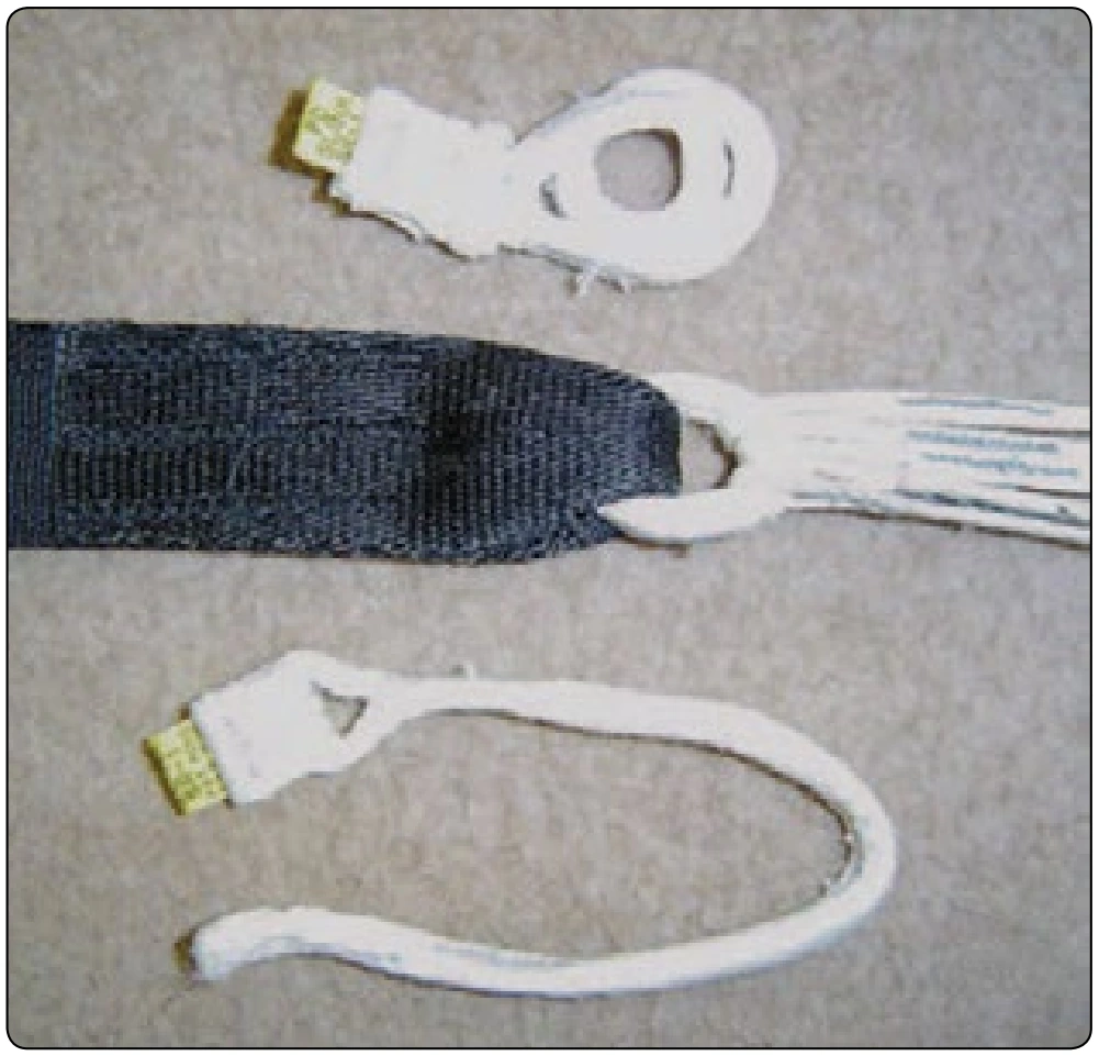
- A type of connector link, called the soft link, is used with certain reserve canopies. [Figure 5-25] Manufactured from Spectra® line, they loop through the bottom of the suspension line and the end of the reserve riser. The strength of these soft links far exceeds that of the metal links when installed properly. If installed on the reserve, the rigger should have the manufacturer’s instructions to ensure the correct installation.
Harness
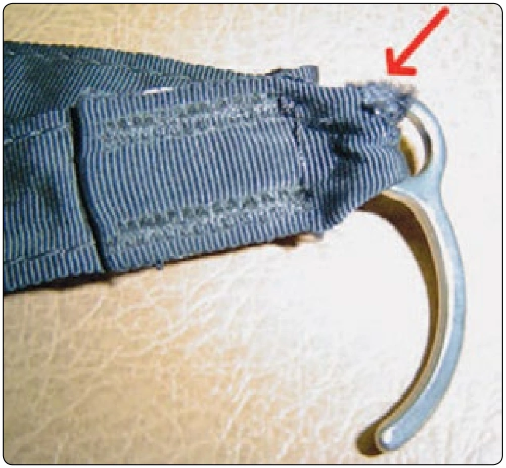
- When inspecting the harness, start at the riser end, checking the condition of the webbing and stitching. Pay particular attention to the security of the steering line guide rings and the method of stowing the excess steering line. If these guide rings fail, it can result in fatal consequences to the user.
- Check all of the hardware on the harness in the same manner detailed in the Pilot Emergency Parachute Section in this chapter.
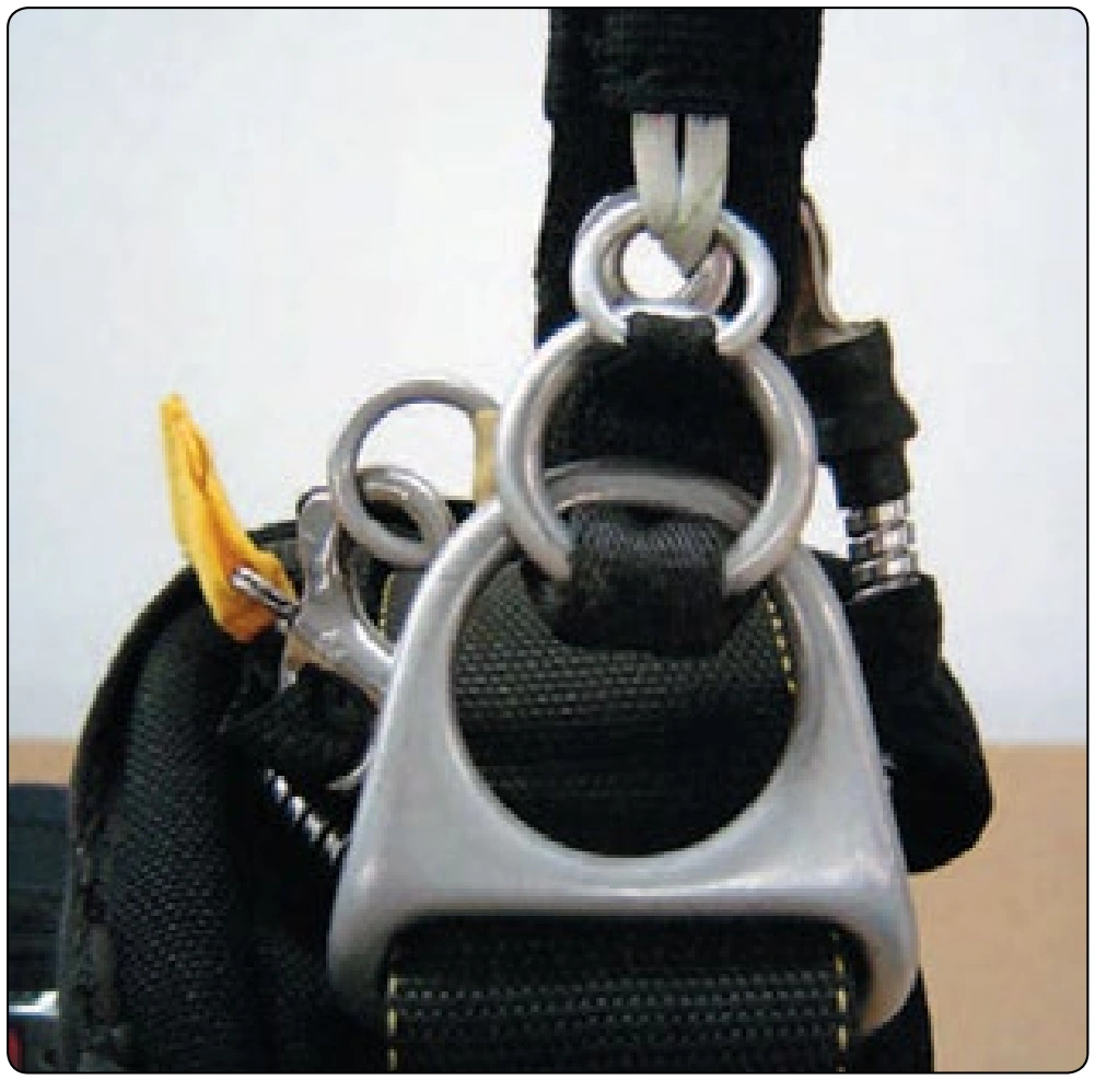
- Check the canopy release system for wear and operation. The release in almost universal use today is the 3-Ring® release system. [Figure 5-26] With this system, it is imperative that the rigger also checks the release cable housings for security and cleanliness. Without proper maintenance, this system can be subject to hard pull forces and the inability to release properly. Since the successful operation of the reserve deployment is somewhat dependent on cleanly releasing the main, a properly operating release system is necessary. The primary areas for inspection are the release locator Velcro® on the harness and the cable housings. Check the housing ends for sharp edges on the inside of the grommets. If the housings are tacked to the harness, make sure these are secure. If the customer did not bring the main canopy with the reserve, the rigger should encourage the customer to at least bring the 3-Ring® release handle in for inspection and service.
Container
In addition to those container areas referenced under the pilot emergency system, the sport piggyback container has features unique to this configuration.
- Check the installation of the AAD, if one is installed, making sure the stowage pockets, cutter mounts, and control unit are secure. Check that the cables are routed correctly. If they are exposed, they may get snagged during packing and damaged or disconnected. Upon completion, inspect the condition of the closing loop.
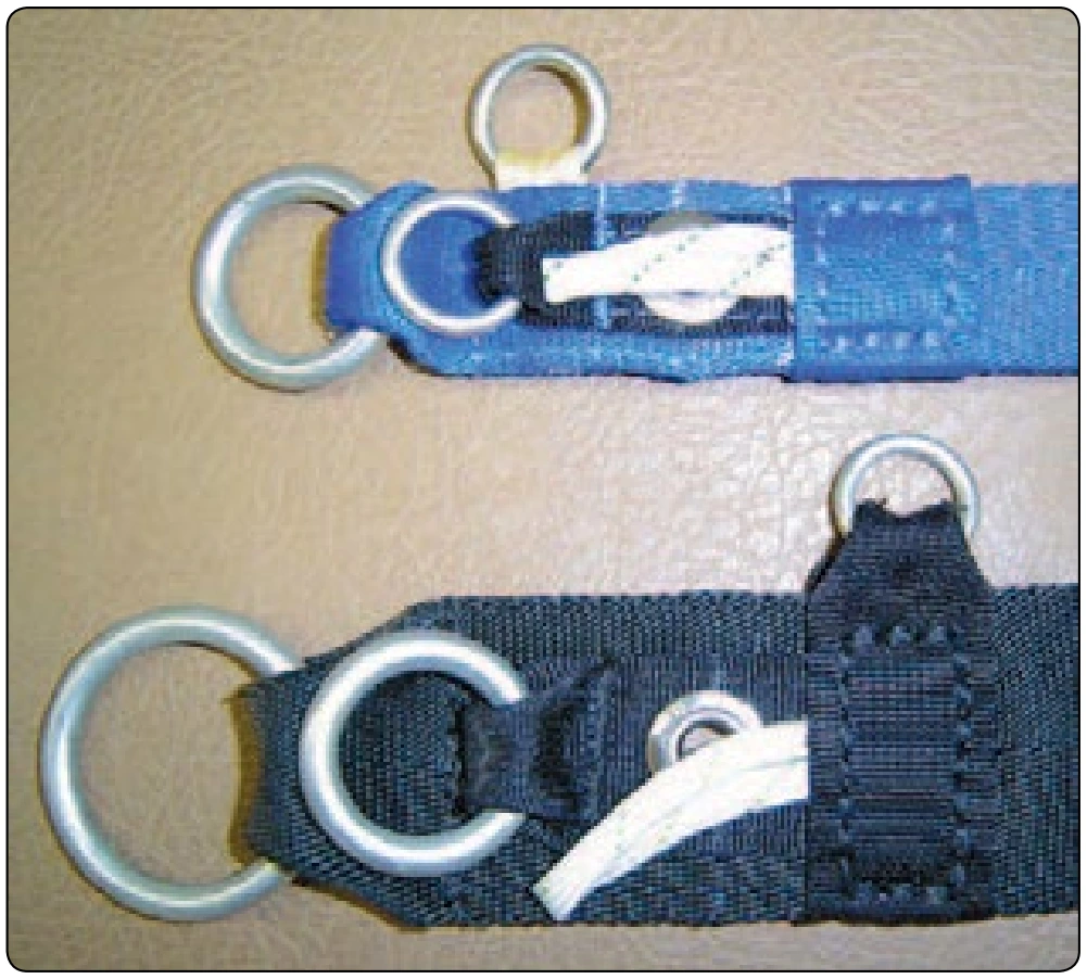
- Check the RSL. The RSL is not considered part of the certified reserve system, but if it is installed, the rigger is responsible for the entire RSL assembly since it is attached to the ripcord handle, cable, or housing. This includes the cable housings for tacking and security, any guide rings used, and the RSL lanyard itself. Check the release or snap shackle, if used, and any Velcro® or other positioning or locating methods. An area frequently overlooked is the RSL attachment ring on the main risers, which are frequently replaced. [Figure 5-27] In many cases, the attachment ring does not match up to the original design. The rigger should inspect the release handle for proper cable lengths. If the design has only one riser attached to the RSL, it is imperative that the cables be trimmed to release the side opposite the lanyard first so that the reserve is not deployed before the risers are separated from the harness.
- Check the main deployment system, of which there are three basic types in use today. The first is a ripcord similar to the pilot emergency system. The second type is the throw-out pilot chute (TOP). The third is the pull-out pilot chute (POP).
- Next, inspect the main ripcord system. Check the ripcord and main pilot chute the same as with the pilot emergency system. Inspect the ripcord pocket for proper holding of the ripcord handle.
- For throw-out pilot chutes, inspect the pilot chute fabric and mesh for holes. Check the TOP handle at the top of the pilot chute for security, paying special attention to the tape holding the handle, which is particularly prone to wear. Check the bridle attachment to the pilot chute. If it is of a centerline collapsible design, check the centerline for wear and stretch and make sure the length of the bridle is correct. Check the curved locking pin for wear or damage as well as the tape, which attaches it to the bridle. [Figure 5-28] Check the pilot chute pocket for fit and wear. Most of today’s installations are what is known as a “bottom of container” (BOC) configuration. It is particularly important that the elastic material from which the pocket is made is in good condition. A loose pocket can result in a premature deployment of the main parachute.
- If repacking a pull-out parachute, check the pilot chute and bridle in the same manner of the throwout parachute inspection. Check the lanyard and handle for wear.