Chapter 7
Repairs, Alterations, and Manufacture
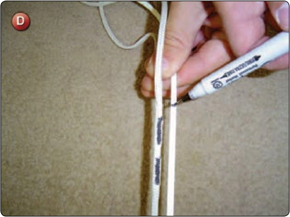
- Cut a piece of line approximately18 inches longer than the original cascade.
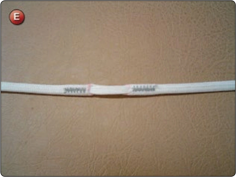
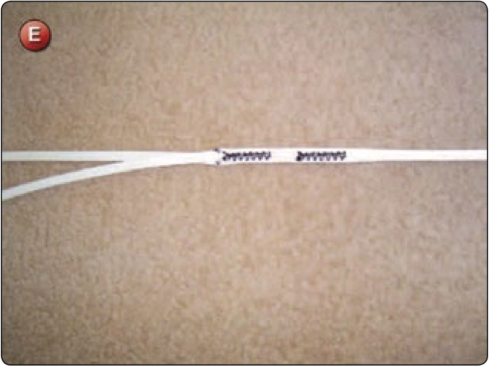
- Finger-trap the cascade into the main line and sew with either a zigzag or bar tack. [Figure E]
- Attach the main line to the line attachment loop as per the original knot configuration.
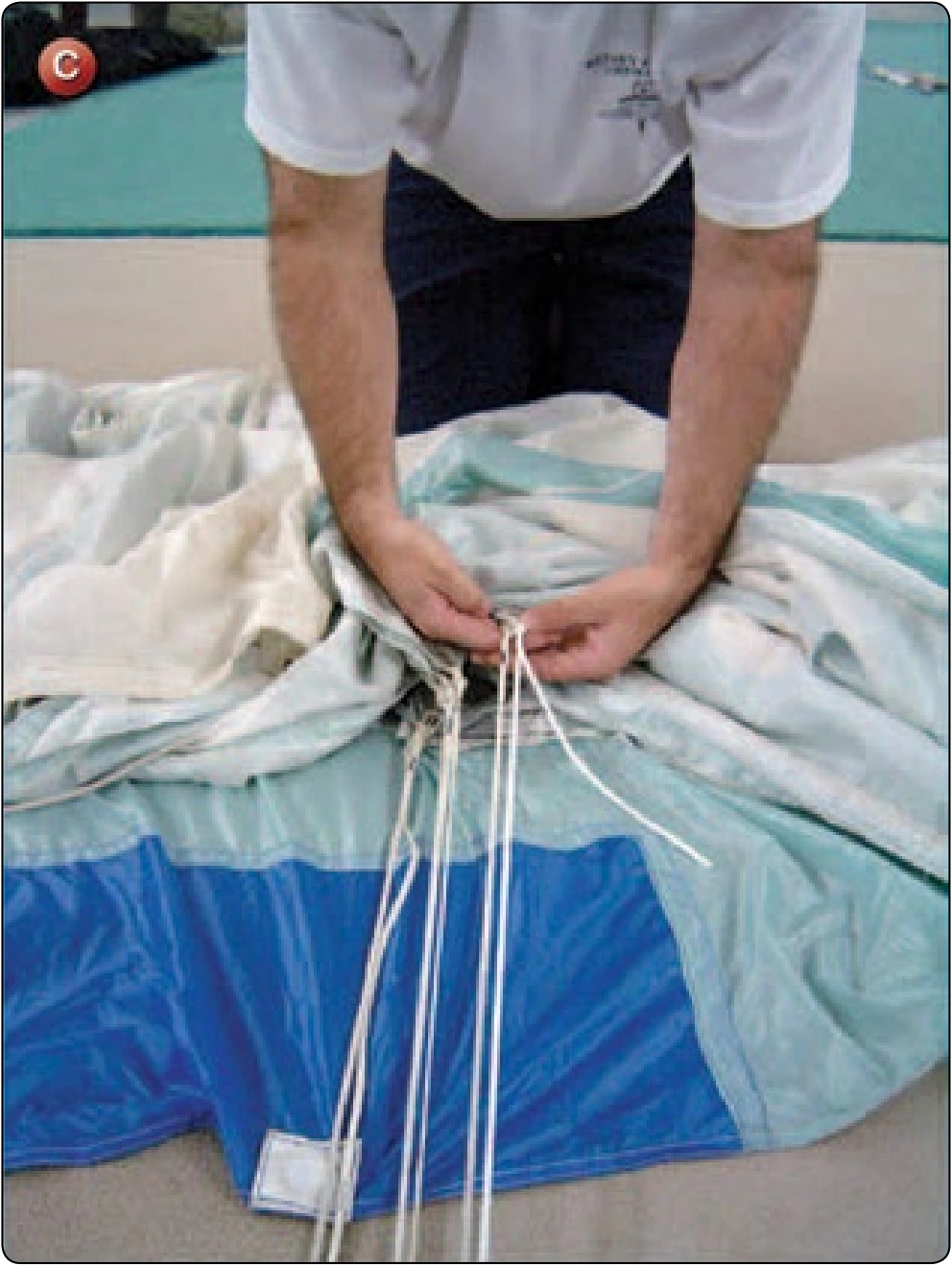
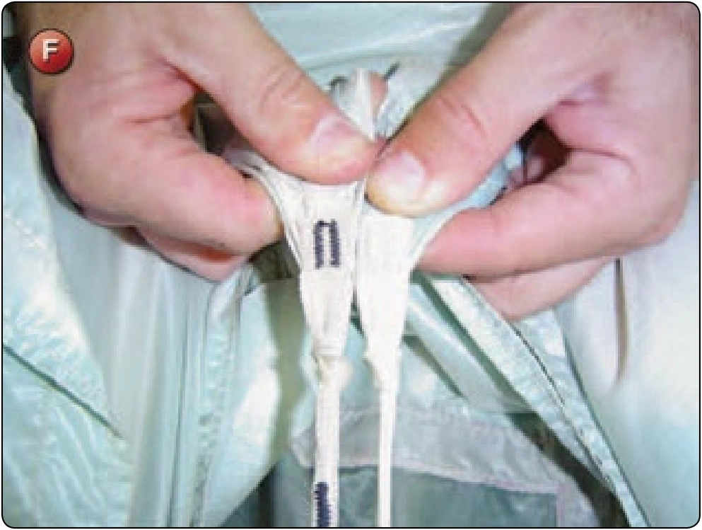
- Tension the line against the adjacent lines and secure the knot. [Figure F] Repeat with the cascade.
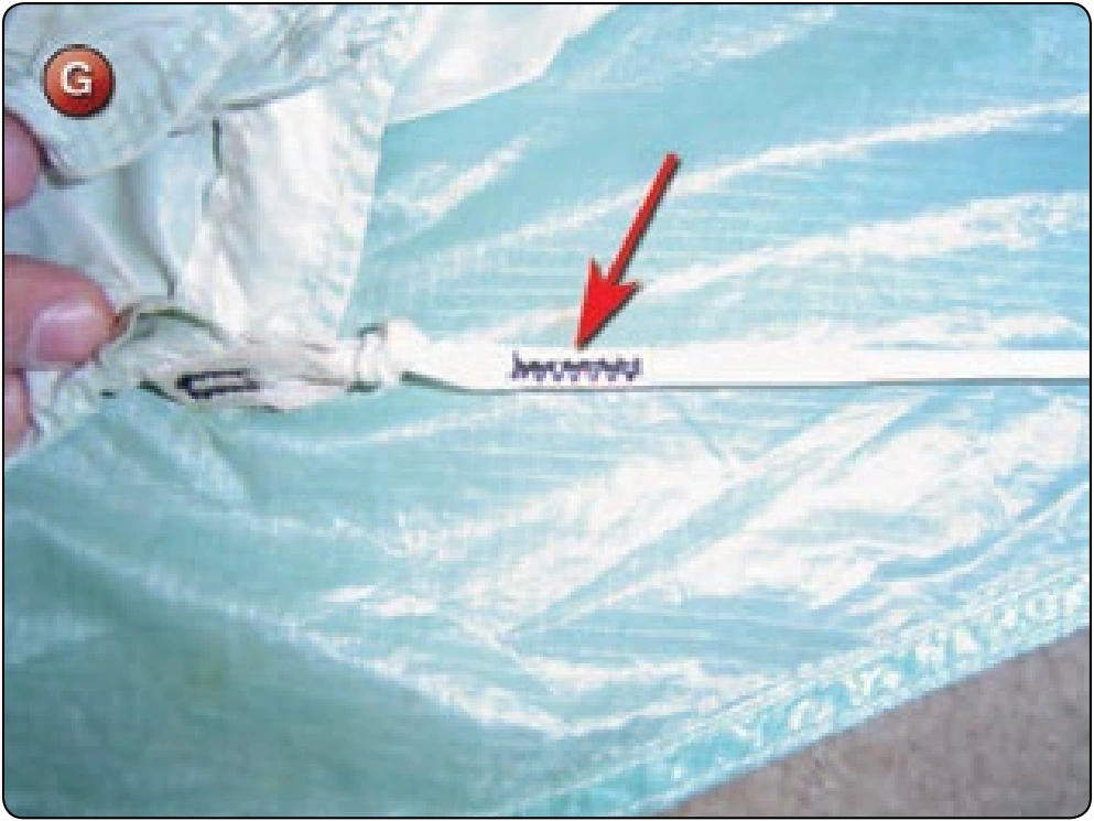
- Finger-trap the running end of the lines and sew with either a zigzag or bar tack. [Figure G]
Inspection
- Check the length of the main line and the cascade line under tension against adjacent lines.
- Check stitching such as zigzag or bar tacks.
- Check line continuity.
Square Canopy—Control Line Replacement
- Applicable products: Square main canopies
- Description: Replacement of the control line assemblies on square main canopies
- Authorized repairmen: FAA Senior or Master Parachute Rigger
- Materials: E thread—color to match; suspension line—type and color to match. Most control line assemblies utilize two or more types of line: one for the upper control lines and a stronger one for the lower control lines.
- Machines: 308 zigzag—medium duty 7–11 SPI and 1 inch × 42 stitch bar tack (optional)
- Equipment: Scissors, seam ripper, marking pencil, 6-inch ruler, tape measure, and small safety pins with marker flags
Procedure
Some manufacturers provide line measurements for their canopies in their owner’s manuals. If so, the rigger should thoroughly measure the control line assembly and compare the measurements against those in the manual. Over time and use, the control lines have a tendency to stretch and change dimensions. At the same time, the rigger needs to compare the right and left side assemblies against each other for any differences. It is not uncommon for the left and right control lines to be different lengths, having been changed to remove a slight turn or change the opening characteristics. Figure A is a sample chart that the rigger can fill in to document the various dimensions needed to repair or replace control lines.
Disassembly
- After measuring the control lines, remove them from one side only. Leave the other side for a reference to check the new lines against both for measurements and construction.
Reassembly
- Determine how many upper control lines there are on the canopy. Four is the most common and this procedure uses this number for the example. With four upper control lines, there are really two continuous lines forming the assembly. Each pair of upper lines is folded in the middle to form two legs of the upper assembly. Each line is therefore measured at twice the A dimension plus 12 inches. If the upper control lines have different lengths, make sure to use the longest measurement to determine the cut length for A. [Figure A]
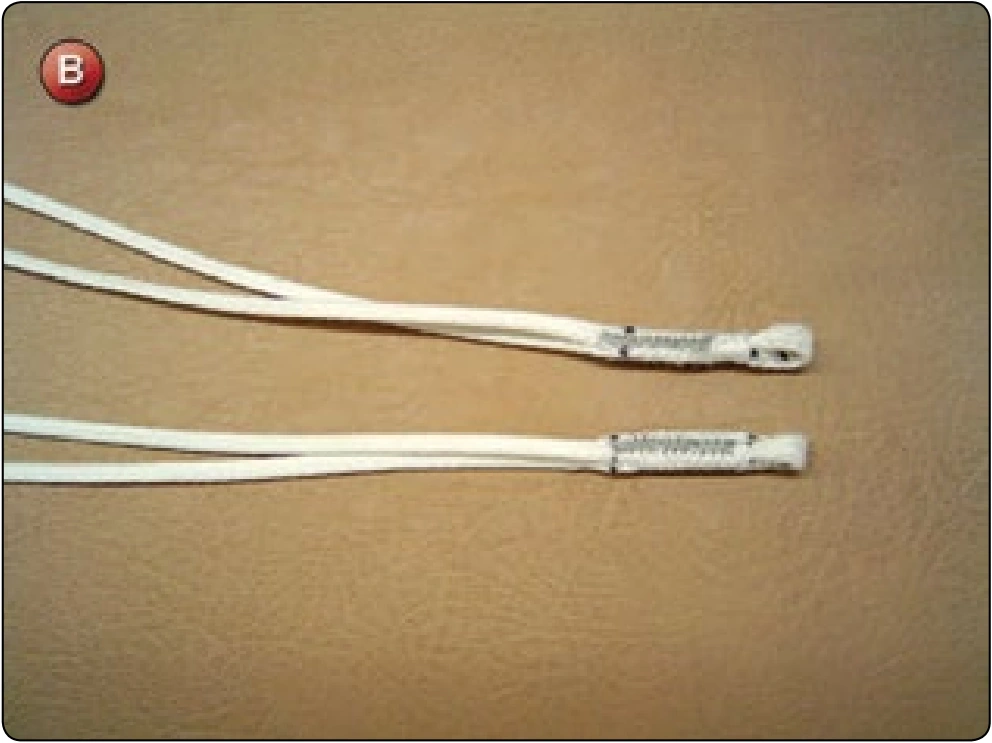
- Using a finger-trapping needle or wire, finger-trap a loop at the center of each of the lines so the result is a line with a loop at the center with two legs extending from it. [Figure B] The eye of the loop should be no more than .25 inch with the fingertrapped portion 1 inch long. Bar tack or zigzag the finger-trapped section.
- There are two types of lower control line configurations: a continuous line and a non-continuous line. The continuous line is one piece with a brake loop finger-trapped into it at the proper location. The noncontinuous line consists of two pieces that form the upper lower and lower lower control line, as well as the brake loop. The continuous line configuration is found primarily on the older generation main canopies and on many of today’s reserve canopies. The noncontinuous configuration is found on most of the modern main canopies due to the ease of replacement because of wear.