Chapter 7
Repairs, Alterations, and Manufacture
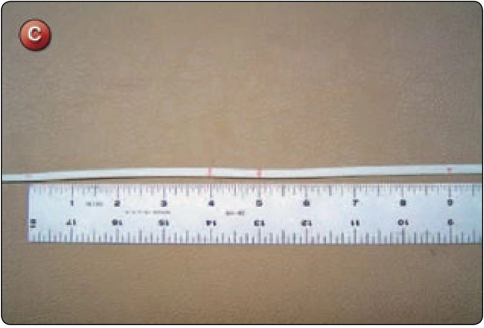
- Take a piece of line used for the lower control line and cut a line equal to the B dimension in Figure A plus 12 inches. On this line, measure from one end 8 inches plus the C dimension from Figure A and mark at that location. This will be the bottom of the brake loop. Mark the brake loop location according to Figure C.
- Take another piece of the lower brake loop line approximately 12 inches long. Finger-trap the brake loop assembly according to Figure
- Make sure the ends are scissor cut and tapered. Bar tack or zigzag the assembly. [Figure E]
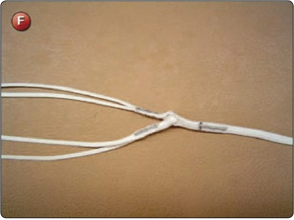
- Measure and mark the C dimension from the bottom of the brake loop. Run the bitter end of the lower control line thru the eyes of two of the upper control lines and finger-trap the line back into itself. [Figure F] Adjust the finger-trap to allow for shrinkage. This completes the continuous line method of lower control line fabrication.
Non-continuous Line Method
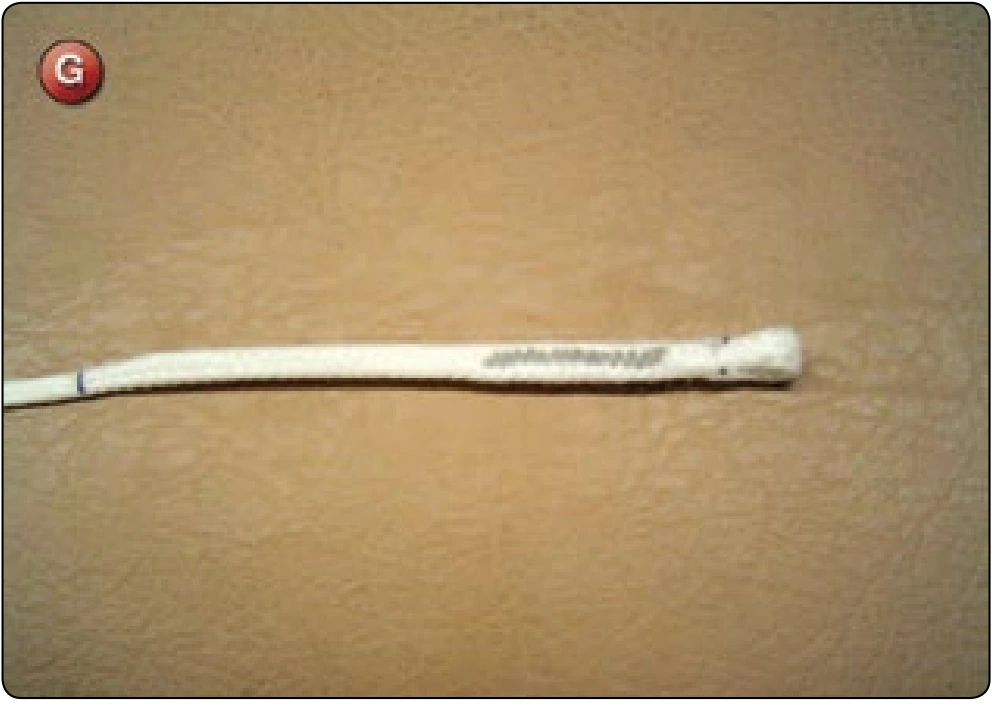
- Take a piece of line used for the lower control line and cut it at the C dimension from Figure A plus 12 inches. Mark at 6 inches from one end and finger-trap a loop .5–1 inch long as per Figure G.
- Take a second piece of control line material and cut it to the D dimension from Figure A plus 12 inches additional. Mark at 6 inches from one end.
- Finger-trap this line thru the loop at the end of the upper lower control line. Make sure there is a minimum of 4 inches finger-trapped in the line and that the lower loop is tight against the upper loop.
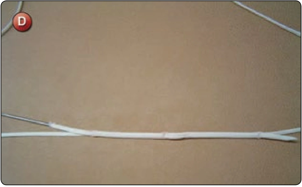
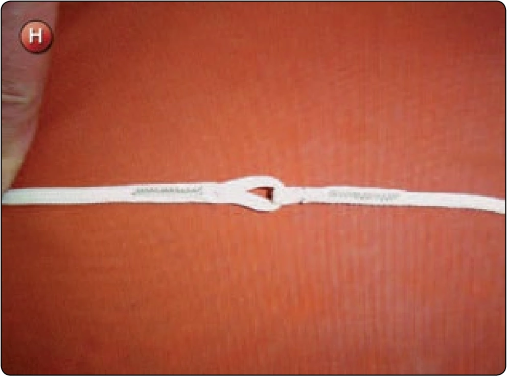
- Bar tack or zigzag the finger-trapped portions to secure them. [Figure H]
- Measure and mark the C dimension from the bottom of the brake loop. Run the bitter end of the lower control line thru the eyes of two of the upper control lines and finger-trap the line back into itself. Adjust the finger-trap to allow for shrinkage. This completes the non-continuous line method of lower control line fabrication.
- Measure the upper control lines according to dimension A plus .5 inch. If the upper control lines are of uneven dimensions, make sure that they are marked accordingly.
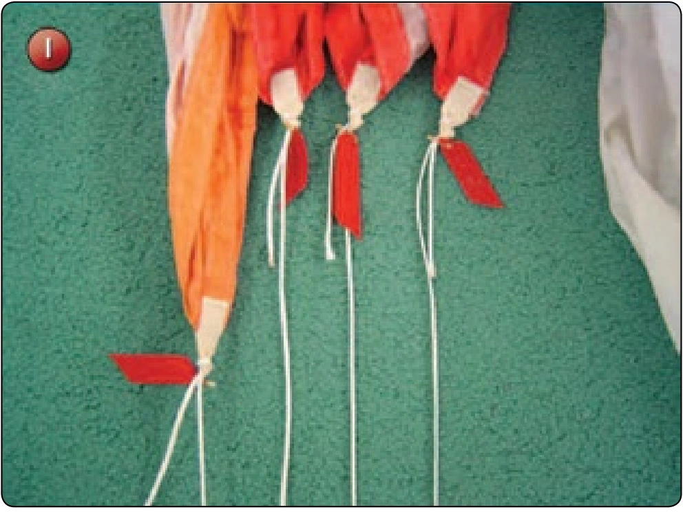
- Lay the canopy on the floor with the trailing edge flat and straight and the line attachment tabs exposed. Lay the upper control lines so that they run to the correct attachment points and route them through the tabs. [Figure I]
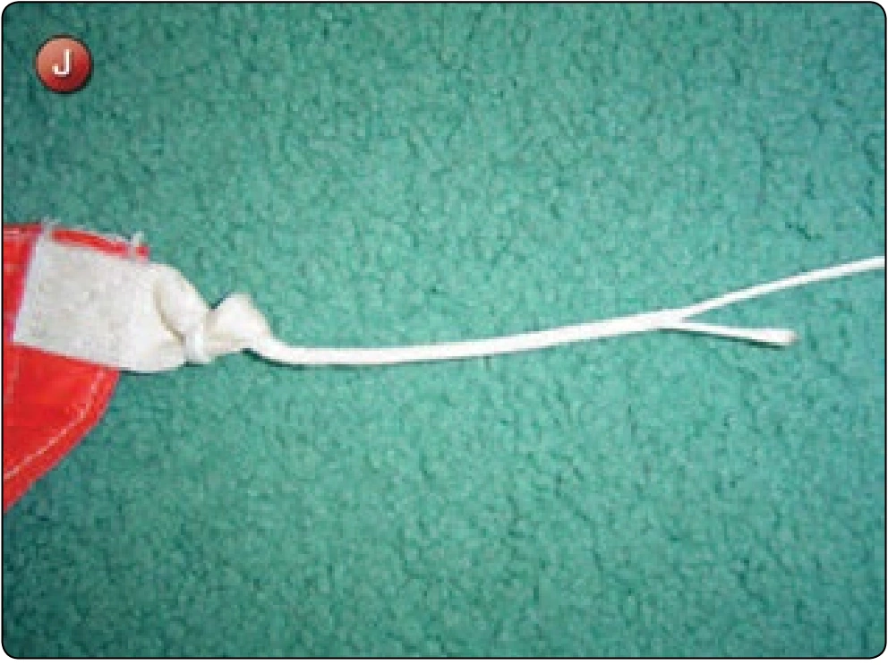
- Make sure that the lines do not have a twist in them and finger-trap the lines back into themselves with a minimum of a 4 inches finger-trap. Leave the running ends exposed. [Figure J] Do not trim the excess line.
- Anchor the brake loop securely and apply tension through the complete control line assembly. Measure the dimension A plus B starting at the outside corner of the trailing edge. Adjust the tension of the finger-trap to allow for shrinkage. Pin the finger-trapped section with a marker flag. [Figure K] Repeat with each upper control line until complete.
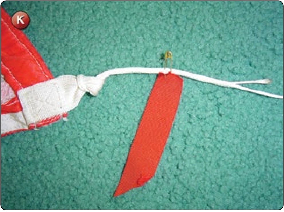
- After setting the dimension for each upper control line, bar tack or zigzag each section. Trim the excess so that the end retreats into the line.
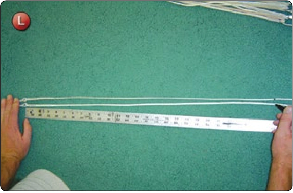
- Measure the dimension D on the lower control line to set the toggle location. [Figure L] If the canopy is on risers, route the lower control line thru the guide ring and tie the steering toggle in place.
Inspection
- Check finished dimensions against original dimensions according to Figure A.
- Check that all finger-trapped junctions are secured with either a bar tack or zigzag.