
Chapter 7
Repairs, Alterations, and Manufacture
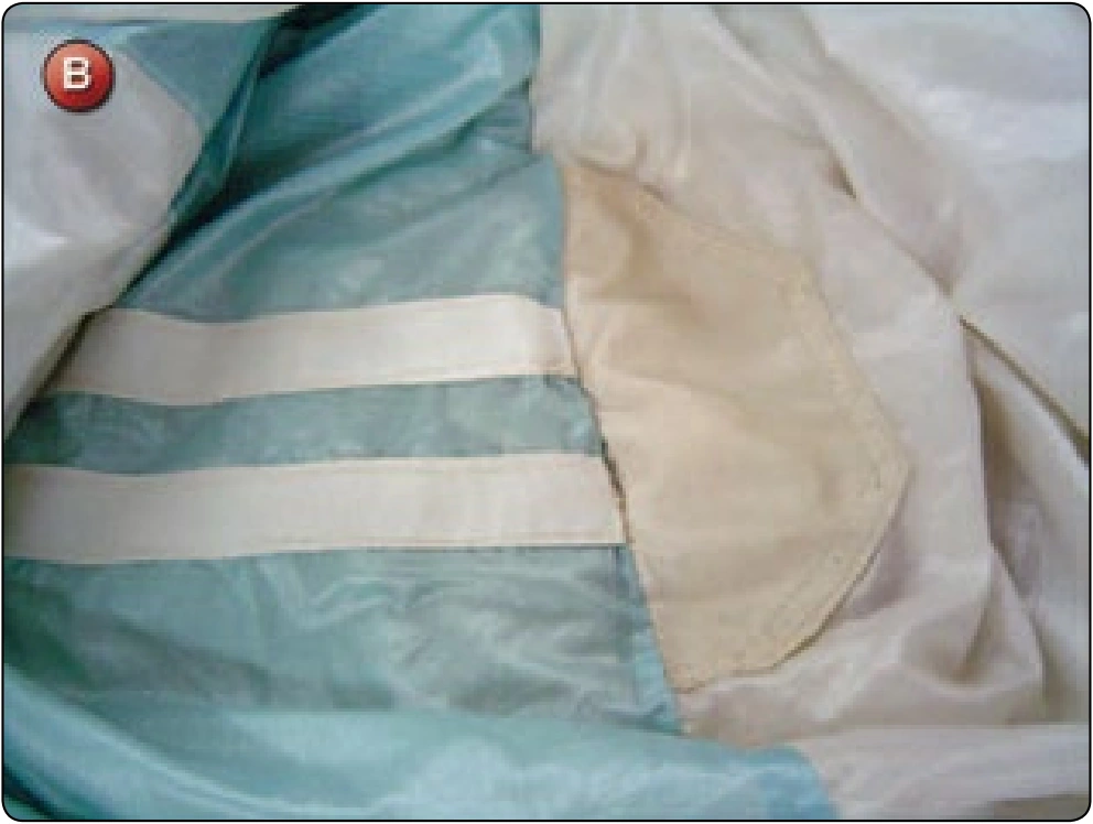
- Detach the top of the rib from the top surface of the cell where the attachment point is located. [Figure C] If the rib is damaged, then a rib repair is needed.
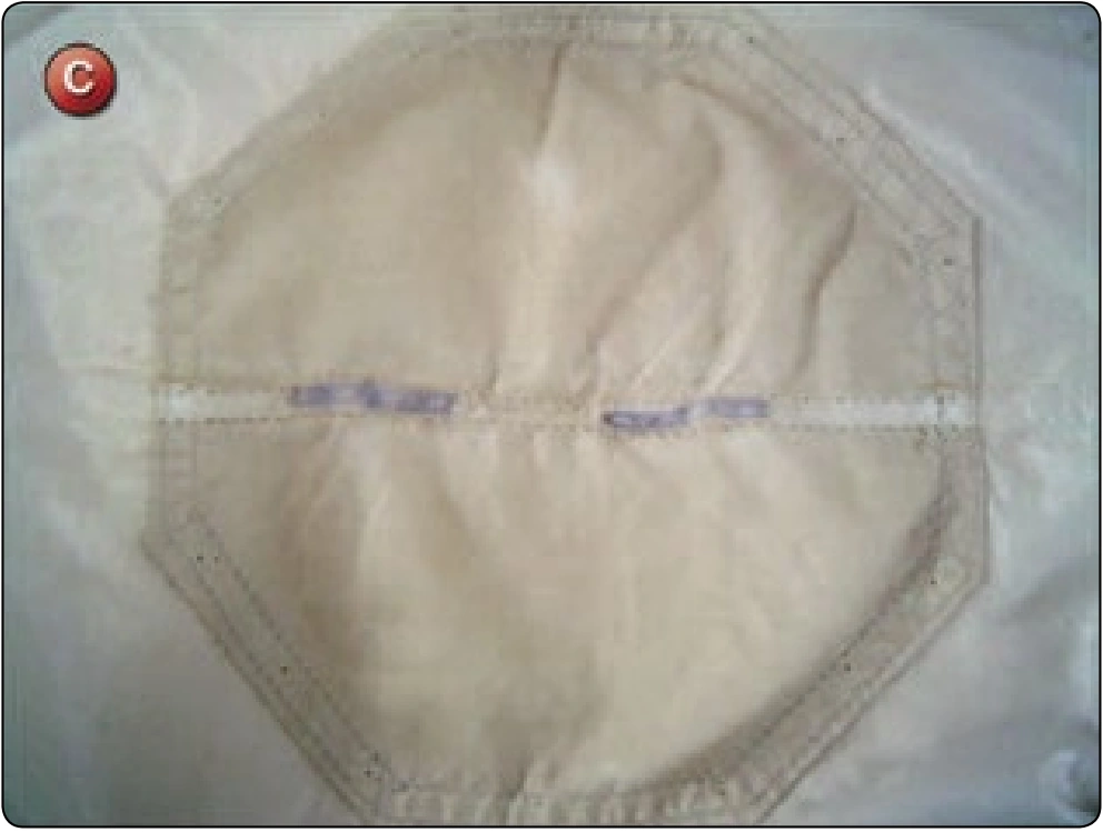
- Usually the top skin of the cell needs to be repaired. Again, depending on the extent of the damage, either perform a patch on the panel or a partial panel replacement.
Reassembly
- After the top skin is repaired, a new reinforcement patch needs to be installed on the center of the cell so that it is centered over the attachment point.
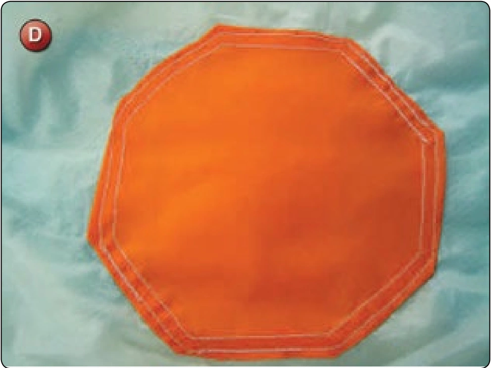
- Take the pre-cut reinforcement panel and sew it in place with two rows of the single-needle machine. The corners should be folded in at a 45 degree angle to eliminate any point loading on the corners. [Figure D]
- Reattach the rib to the top surface of the canopy as per the original configuration.
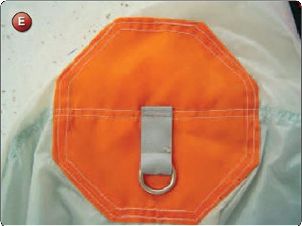
- Install a new pilot chute attachment tape and ring at the appropriate location. [Figure E]
Inspection
- Check that rib and panel repairs have been made as needed.
- Verify the new top reinforcing panel is in place with two rows of single-needle stitching.
- Check the new attachment tape and ring for the appropriate stitch pattern.
Round Canopy—Non-continuous Line Replacement
- Applicable products: Round canopies—main and reserve.
- Description: Replacement of a suspension line on a round canopy with non-continuous line configuration.
- Authorized repairmen: FAA Master Parachute Rigger
- Materials: E thread; Suspension line—type and color to match
- Machines: 308 zigzag—medium duty 7–11 SPI, 1 inch × 42 stitch bar tack (optional)
- Equipment: Packing table, scissors, seam ripper or scalpel, marking pencil, 6-inch ruler, 60-pound fish scale or equivalent, and finger-trapping needle
Procedure
The most common need for this type of repair today is as a result of the suspension line of the reserve being damaged during packing or occasionally during use after landing.
The newer, lightweight braided lines are very susceptible to being snagged on the hook portion of Velcro® closures on the container if care is not taken by the rigger.